
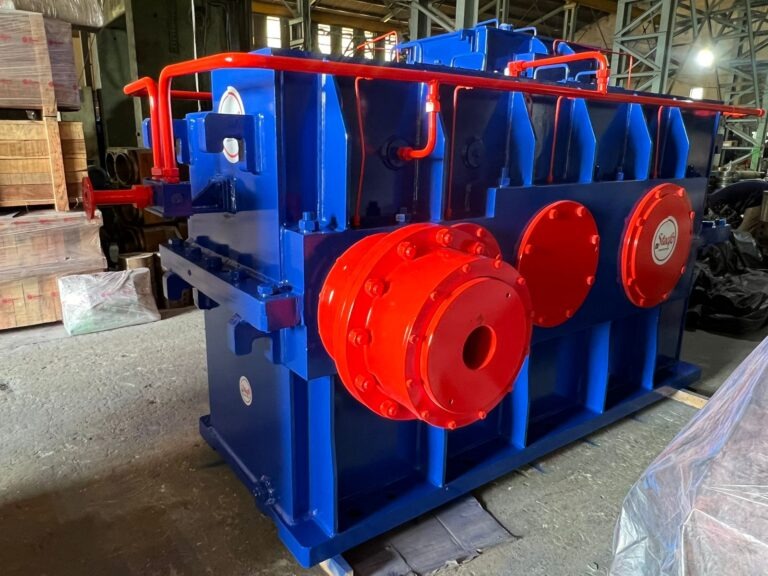
Specifying the wrong gearbox type for a mill stand doesn’t usually fail immediately — it shows up months later as excessive wear, higher-than-expected noise, or a shorter service life than the equipment should deliver. With rolling mills running multi-shift, multi-year production campaigns, the gearbox type decision made at the specification stage has consequences that outlast the original purchase order by years.
Rolling mill gearboxes fall into three main types based on gear design: reduction gearboxes, which use helical or spur gears to reduce motor speed while increasing torque; pinion gearboxes, which split power from a single input to multiple roll outputs; and worm gearboxes, which use a worm-and-wheel arrangement to achieve large reduction ratios in a compact footprint.
Each type suits a different point in the mill’s drive-train, and choosing between them isn’t about which is “better” — it’s about matching gear design to the specific torque, speed, and layout requirements of that stand. This guide focuses on that decision: what each type is genuinely best suited for, and how to match gearbox type to your mill stand configuration.
Why Gearbox Type Affects Mill Performance
A rolling mill’s drive-train has to deliver very high torque at relatively low speed to the rolls, while the motor driving it typically runs at a much higher speed. The gearbox is what bridges that gap — and different gear designs bridge it with different trade-offs in efficiency, noise, load capacity, and physical footprint.
This is also where drive-train design connects directly to the equipment already covered in a mill’s specification — the mill stand configuration a plant runs determines how many synchronized roll outputs each gearbox needs to support, which is precisely why gearbox type can’t be chosen independently of the stand it serves.
Getting this wrong isn’t cosmetic. A gearbox undersized for the torque a stand actually generates wears out its gear teeth faster than specification predicts. One oversized for the application adds unnecessary cost and footprint without a performance benefit. The type decision and the sizing decision are connected — but the type has to be right first, because it determines what sizing options even exist.
This distinction matters more on a rolling mill than on most other industrial machinery because gearboxes here run continuously across multi-shift production, often for years between planned overhauls. A gear design mismatched to its actual duty cycle doesn’t announce itself immediately — it shows up gradually as increased vibration, higher operating temperature, and eventually a shortened service life that forces an unplanned rebuild well ahead of schedule.
Reduction Gearboxes
How They Work
A reduction gearbox uses a set of helical or spur gears arranged so the output gear has more teeth than the input gear, slowing rotational speed while proportionally increasing torque. This is the most common gearbox type across the mill’s main drive line, sitting directly between the motor and the pinion stand.
Best Suited For
Reduction gearboxes are the default choice for main drive applications where a single motor needs to deliver high torque to the rolling line at a controlled, steady speed — TMT bar and structural mill main drives being the most common example. Their straightforward gear arrangement also makes them easier to service and rebuild over the equipment’s operating life compared to more complex configurations.
Because a reduction gearbox typically carries the highest sustained load of any gearbox on the mill, gear quality here has an outsized effect on overall drive-train reliability. Hardened and ground gear teeth, precise center-distance control between shafts, and adequate lubrication capacity all matter more on a main reduction gearbox than on the lighter-duty gearboxes elsewhere in the line.
Pinion Gearboxes
How They Work
A pinion gearbox takes power from a single input shaft and splits it to drive two roll outputs — typically the top and bottom rolls of a stand — keeping both rolls synchronized at the correct speed ratio. It sits downstream of the main reduction gearbox in the drive-train, immediately before the roll stand itself.
Best Suited For
Pinion gearboxes are essential wherever a stand has two (or more) driven rolls that must stay precisely synchronized — which is the case across most 2-Hi and multi-roll rolling mill stands. Because timing accuracy between rolls directly affects product dimensional consistency, gear quality and backlash control matter more here than in a single-output reduction gearbox.
The bevel gear design used in many pinion gearboxes also has to tolerate the shock loading that occurs when an incoming billet or bar first enters the roll pass — a load spike the reduction gearbox further upstream is partially insulated from by the pinion stand sitting between them. This is why pinion gearbox specification often prioritizes toughness and shock resistance alongside pure torque capacity.
Worm Gearboxes
How They Work
A worm gearbox uses a screw-like “worm” meshing with a toothed wheel to achieve very high reduction ratios in a compact housing, with input and output shafts arranged at right angles to each other. The design is inherently self-locking in many configurations — the output side can’t drive the worm backward, which acts as a built-in safety feature.
Best Suited For
Worm gearboxes suit lower-power auxiliary drives where space is constrained and a large reduction ratio is needed from a small input torque — pinch roll drives, roller table adjustments, and similar auxiliary mechanisms rather than the main rolling line itself. They’re generally not specified for high-power main drives, since worm gearing is less efficient at transmitting power than helical reduction gearing of equivalent capacity.
The self-locking behavior that makes worm gearboxes attractive for adjustment mechanisms comes with a trade-off worth knowing before specifying one: the efficiency loss that creates self-locking also generates more heat per unit of power transmitted than helical gearing, which is part of why worm gearboxes are rarely a good fit once power requirements climb into main-drive territory.
How to Match Gearbox Type to Your Mill Stand Configuration
Use the drive-train position as the starting point for the decision, not the other way around. Main drive line, between motor and pinion stand: reduction gearbox. Splitting power to two synchronized roll outputs at the stand itself: pinion gearbox. Low-power auxiliary mechanism with tight space constraints: worm gearbox. Most rolling mills use two or even all three types across different points in the same line — the question is rarely “which type should our mill use” but “which type belongs at this specific position.”
Beyond position, three practical factors should shape the final specification for each gearbox: the actual torque and speed profile at that point (not just the motor’s rated output), the duty cycle — continuous multi-shift running versus intermittent auxiliary use — and the maintenance access available at that location in the mill layout, since a gearbox buried deep in a compact stand assembly needs a different serviceability standard than one mounted for easy access. Skipping any one of these and specifying by gearbox type alone is how mills end up with equipment that’s technically correct on paper but underperforms in practice.
| Gearbox Type | Typical Position | Strength | Watch-Out |
|---|---|---|---|
| Reduction Gearbox | Main drive, motor to pinion stand | High torque capacity, straightforward maintenance | Sizing must match actual torque demand, not motor rating alone |
| Pinion Gearbox | At the stand, splitting to top/bottom rolls | Precise roll synchronization | Backlash control is critical — poor quality shows up as product dimension variation |
| Worm Gearbox | Auxiliary drives, pinch rolls, roller tables | Compact, high ratio, self-locking | Lower power-transmission efficiency — not suited to main drive loads |
Choosing between reduction, pinion, and worm gearboxes for a rolling mill comes down to matching gear design to where the component sits in the drive-train, not picking a single “best” type for the whole line. Reduction gearboxes carry the main drive load, pinion gearboxes keep roll pairs synchronized at the stand, and worm gearboxes handle compact, lower-power auxiliary mechanisms. Getting each position right at the specification stage is what prevents the gradual wear and premature replacement that comes from a mismatched gearbox type.
Frequently Asked Questions
What is the difference between a reduction gearbox and a pinion gearbox?
A reduction gearbox reduces motor speed while increasing torque for a single output shaft, typically on the main drive line. A pinion gearbox takes a single input and splits it to drive two or more roll outputs in synchronization, and sits at the stand itself rather than on the main drive line.
Can a worm gearbox be used for a rolling mill’s main drive?
It’s uncommon. Worm gearboxes are less efficient at transmitting high power than helical reduction gearing of equivalent capacity, which is why they’re typically specified for lower-power auxiliary drives like pinch rolls rather than the main rolling line.
How do I know what gearbox type my mill stand needs?
Start with the drive-train position: main line between motor and pinion stand needs a reduction gearbox, splitting power to synchronized roll outputs needs a pinion gearbox, and compact auxiliary mechanisms typically suit a worm gearbox. Your equipment manufacturer’s engineering team can confirm the right type for your specific mill configuration.
Why do rolling mill gearboxes wear out faster than expected?
This is most often traced back to a mismatch between gearbox type or sizing and the actual torque demand at that position in the drive-train, rather than the gearbox itself being poor quality. Under-specifying capacity for the real operating load accelerates gear tooth wear regardless of gearbox type.
Does Steefo manufacture all three gearbox types?
Yes. Steefo designs and manufactures reduction and pinion gearboxes as part of its rolling mill equipment range, engineered to the torque and speed requirements of the specific mill stand they’re supplying. Contact our engineering team with your drive-train configuration for a matched specification.
Get in Touch
To get help matching gearbox type to your mill’s drive-train configuration, see our full range on the rolling mill gearbox product page, read our guide on rolling mill gearbox care, or reach out to our engineering team directly. Call us at +91 98240 76873 or write to marketing@thesteefogroup.com.