Categories
Blogs Mill Stands

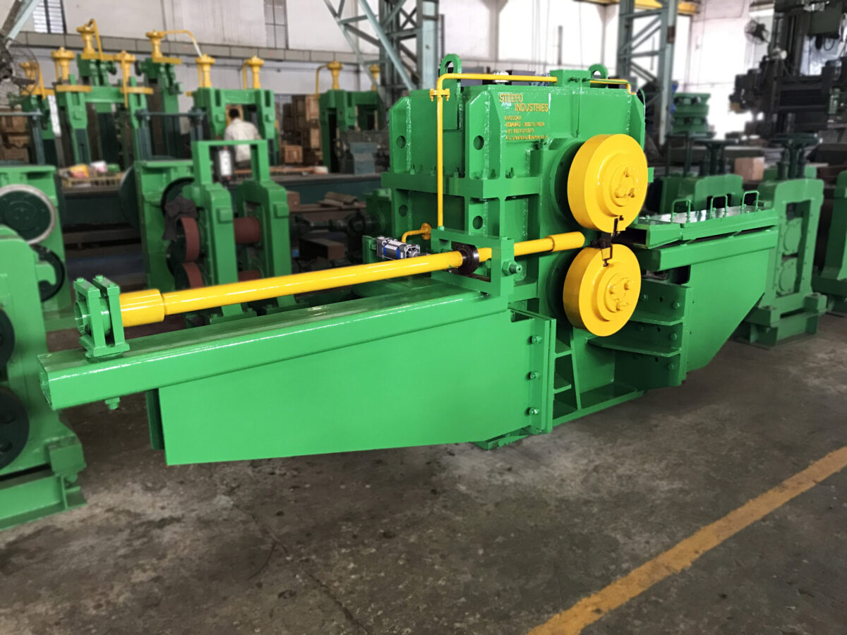
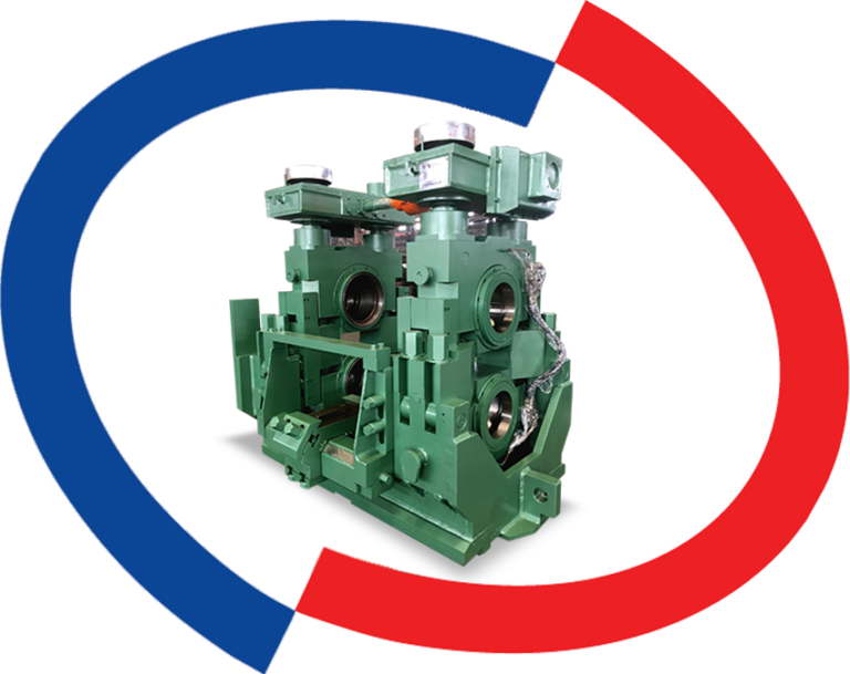
A mill stand carries the full rolling load of a hot rolling mill — every pass, every shift, for years without failure being an option. When a plant evaluates a new supplier, the question isn’t just what the stand costs; it’s how it was actually built, because that manufacturing process is what determines whether the stand holds tolerance under repeated high-load cycles or develops play and misalignment within a few years.

Mill stand manufacturing is the process of converting raw material — cast iron, cast steel, or fabricated steel plate — into a finished housing and roll-assembly structure through pattern-making, casting or fabrication, precision machining, assembly, and load testing, following a sequence that determines the stand’s final rigidity and alignment accuracy.

The process a manufacturer follows directly determines the stand’s rigidity, alignment accuracy, and service life under continuous rolling loads.

This guide walks through how rolling mill stands are actually manufactured — material selection, the production process step by step, and the quality checks a stand must pass before it leaves the factory — so you know what to ask when evaluating a manufacturer.

This matters more for structural and TMT bar mills running continuous multi-shift production than it might for lighter-duty applications, because a stand here rarely gets a genuine break between passes. The manufacturing decisions made before a stand ever reaches the mill floor are what determine whether it holds tolerance through years of that duty cycle or begins drifting within its first eighteen months.

Why Manufacturing Quality Determines Mill Stand Lifespan

A mill stand’s job is to hold two rolls in precise alignment while resisting the separating force generated as steel passes between them — a force that runs into hundreds of tonnes on a structural or TMT bar mill. If the housing flexes even slightly under that load, roll alignment drifts, and the result shows up downstream as dimensional inconsistency in the finished bar.

This is why manufacturing quality isn’t a finishing-touch consideration — it’s structural. A stand cast with internal porosity, or machined without verifying squareness between the housing windows, may pass a basic visual inspection and still fail to hold tolerance once it’s under real rolling load for a few months.

The practical consequence shows up gradually rather than as a sudden failure, which is part of why it’s easy to underweight at the ordering stage. A stand with a marginal casting defect or slightly out-of-tolerance housing window typically performs acceptably for the first few months. Wear then accelerates at the point of weakness, roll alignment drifts a little further with every pass, and by the time it shows up as a quality problem in the finished bar, the root cause is buried months in the past — and far harder to trace back to a manufacturing decision than it would have been to catch with proper testing before dispatch.

Material Selection for Mill Stand Fabrication

The starting material determines both the manufacturing route and the stand’s long-term behavior under load.

Cast Iron vs Cast Steel vs Fabricated Steel

Cast iron housings are common on lighter, older mill designs — they’re straightforward to produce in a single-piece pour but carry more risk of internal casting defects and generally lower toughness than cast steel. Cast steel housings, used widely on modern roughing and intermediate stands, offer significantly better toughness and resistance to shock loading, which matters when a mill trips or an oversized billet enters the pass. Fabricated steel housings — welded from forged steel plate rather than cast in one piece — skip the pattern-and-mold stage entirely, which shortens lead time and avoids casting-related defects, at the cost of requiring precise weld sequencing to control distortion.

The choice isn’t purely a cost decision. A roughing stand absorbing the highest separating forces in the mill is generally better served by cast steel’s toughness, while a finishing stand — handling lighter loads but requiring tighter dimensional accuracy — can sometimes be well served by a fabricated design if weld quality and stress-relief are properly controlled. Reputable manufacturers select the route based on the stand’s position in the rolling sequence, not a single default material across the whole mill.

Closed-type housings, cast as a single rigid frame, are generally specified for heavy roughing stands where maximum stiffness matters most. Open-type housings, with a removable top cap, trade a small amount of rigidity for significantly faster roll-change time — a relevant factor for mills running frequent product changeovers.

The Manufacturing Process Step-by-Step

Regardless of material route, a mill stand goes through the same broad sequence before it’s ready to ship.

Pattern-Making & Casting (or Fabrication)

For cast housings, a pattern is produced first — traditionally in wood or resin, increasingly via CAD-driven pattern design — and used to create the sand mold the housing is poured into. For fabricated housings, forged steel plates are cut to profile and prepared for welding according to a controlled sequence designed to minimize distortion.

Stress Relief

Both cast and welded housings carry internal stresses from the casting or welding process itself — stresses that, left unaddressed, release slowly over time and cause dimensional movement after the stand is already machined and in service. Heat-treatment stress relief before machining is what prevents this, and it’s a step that’s straightforward to skip under time pressure but difficult to detect until the stand is already installed and drifting.

Machining & Precision Boring

Once the rough casting or weldment has stress-relieved, it moves to machining, where the critical surfaces are cut to final dimension: the housing windows that locate the roll chocks, the base mounting faces, and the bores for adjustment screws. This is the stage where tolerance is actually created — a housing window bored even a fraction of a millimeter out of parallel will show up as uneven roll wear later.

Assembly & Fitting

Roll chocks, adjustment mechanisms, and bearing housings are fitted into the machined stand and checked for free movement without play. On stands with screw-down or hydraulic adjustment, this stage also confirms the adjustment mechanism moves through its full range without binding.

Quality Checks & Testing Before Dispatch

A mill stand that looks correct on the shop floor still has to prove it under conditions that approximate actual rolling load before it’s cleared for dispatch.

Dimensional Accuracy Checks

Housing window parallelism, base flatness, and bore alignment are verified against drawing tolerances using coordinate measuring or precision gauging — not just a visual and tape-measure check. For stands manufactured for TMT bar and structural mills, this verification directly determines whether the finished bar will meet dimensional tolerance once the stand is installed.

Material & Load Testing

Cast components are checked for internal defects — porosity, shrinkage cavities, or cracks — typically through ultrasonic or dye-penetrant testing on critical load-bearing sections. Material certificates confirming the correct grade and heat treatment should accompany every stand, and a reputable manufacturer will provide these without being asked.

Some manufacturers go further and simulate service load on a test rig before dispatch, checking for deflection under a controlled force approximating the stand’s rated separating force. This isn’t universal practice — it adds time and cost to the manufacturing cycle — but for a Tier-1 structural component like a roughing stand, it’s the closest a buyer can get to proof of performance before the stand is actually installed and running production.

What to Ask Your Mill Stand Manufacturer Before Ordering

Before finalizing an order, ask specifically: what material grade and casting or fabrication method is used for this stand type, what dimensional tolerances are held on the housing windows, and what testing (ultrasonic, dye-penetrant, load testing) is performed before dispatch. A manufacturer with a mature quality process will have specific, documented answers to all three — vague reassurance is itself a signal worth noting.

It’s also worth asking how the manufacturer’s stand design interacts with your specific mill stand configuration — housingless designs are manufactured and machined differently from conventional closed housings, and a supplier experienced with both will be able to explain the trade-off for your application rather than defaulting to whichever they build most often.

Question What a Strong Answer Looks Like
Material grade & route Specific grade (e.g., cast steel to a stated specification) with a documented reason for the choice given your mill type
Dimensional tolerance held Numeric tolerance figures for housing window parallelism and bore alignment, not “high precision”
Pre-dispatch testing Named tests performed (ultrasonic, dye-penetrant, load test) with certificates provided as standard
Lead time & capacity A specific timeline tied to your stand configuration, not a generic range

Understanding how a mill stand is actually manufactured changes the conversation with a supplier from “what does it cost” to “what am I actually getting for that cost.” The stands that hold tolerance for years under continuous rolling load are the ones where material selection, machining precision, and pre-dispatch testing were treated as engineering requirements, not finishing steps. That’s the standard worth asking every mill stand manufacturer to meet.

Frequently Asked Questions

What material is best for rolling mill stand housings?

It depends on the application. Cast steel offers the best combination of toughness and rigidity for most roughing and intermediate stands, while fabricated steel housings can offer shorter lead times for certain configurations. Cast iron is still used on lighter or older mill designs but generally offers lower shock resistance than cast steel.

How long does it take to manufacture a mill stand?

Lead time depends on the housing type, size, and whether it’s cast or fabricated. Cast housings typically require longer lead times due to pattern-making and casting stress-relief, while fabricated housings can sometimes be produced faster since they skip the mold stage entirely.

What quality tests should a mill stand pass before dispatch?

At minimum, dimensional accuracy checks on housing windows and mounting faces, plus material integrity testing — ultrasonic or dye-penetrant inspection — on critical load-bearing sections. Material certificates confirming grade and heat treatment should be provided with every stand.

Why do some mill stands lose alignment after a few years of use?

This is usually traced back to the manufacturing stage rather than operational wear alone — internal casting defects, insufficient stress-relief before machining, or housing windows machined outside tolerance all show up over time as drift in roll alignment under sustained load.

Does Steefo manufacture custom mill stands for specific mill configurations?

Yes. Steefo designs and manufactures mill stands — including housingless and conventional configurations — matched to a plant’s specific rolling requirements. Contact our engineering team with your mill configuration for a tailored specification.

Get in Touch

To discuss a mill stand manufacturing specification for your rolling mill, see how our stands are engineered on the mill stands product page, read more on what sets our stands apart in The Steefo Advantage: Mill Stands Built to Last, or reach out to our team directly. Call us at +91 98240 76873 or write to marketing@thesteefogroup.com.
Categories
Blogs Gearbox

Specifying the wrong gearbox type for a mill stand doesn’t usually fail immediately — it shows up months later as excessive wear, higher-than-expected noise, or a shorter service life than the equipment should deliver. With rolling mills running multi-shift, multi-year production campaigns, the gearbox type decision made at the specification stage has consequences that outlast the original purchase order by years.

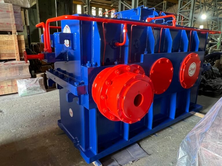
Rolling mill gearboxes fall into three main types based on gear design: reduction gearboxes, which use helical or spur gears to reduce motor speed while increasing torque; pinion gearboxes, which split power from a single input to multiple roll outputs; and worm gearboxes, which use a worm-and-wheel arrangement to achieve large reduction ratios in a compact footprint.

Each type suits a different point in the mill’s drive-train, and choosing between them isn’t about which is “better” — it’s about matching gear design to the specific torque, speed, and layout requirements of that stand. This guide focuses on that decision: what each type is genuinely best suited for, and how to match gearbox type to your mill stand configuration.

Why Gearbox Type Affects Mill Performance

A rolling mill’s drive-train has to deliver very high torque at relatively low speed to the rolls, while the motor driving it typically runs at a much higher speed. The gearbox is what bridges that gap — and different gear designs bridge it with different trade-offs in efficiency, noise, load capacity, and physical footprint.

This is also where drive-train design connects directly to the equipment already covered in a mill’s specification — the mill stand configuration a plant runs determines how many synchronized roll outputs each gearbox needs to support, which is precisely why gearbox type can’t be chosen independently of the stand it serves.

Getting this wrong isn’t cosmetic. A gearbox undersized for the torque a stand actually generates wears out its gear teeth faster than specification predicts. One oversized for the application adds unnecessary cost and footprint without a performance benefit. The type decision and the sizing decision are connected — but the type has to be right first, because it determines what sizing options even exist.

This distinction matters more on a rolling mill than on most other industrial machinery because gearboxes here run continuously across multi-shift production, often for years between planned overhauls. A gear design mismatched to its actual duty cycle doesn’t announce itself immediately — it shows up gradually as increased vibration, higher operating temperature, and eventually a shortened service life that forces an unplanned rebuild well ahead of schedule.

Reduction Gearboxes

How They Work

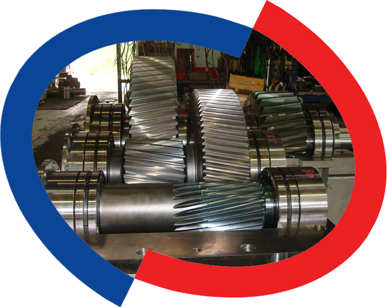
A reduction gearbox uses a set of helical or spur gears arranged so the output gear has more teeth than the input gear, slowing rotational speed while proportionally increasing torque. This is the most common gearbox type across the mill’s main drive line, sitting directly between the motor and the pinion stand.

Best Suited For

Reduction gearboxes are the default choice for main drive applications where a single motor needs to deliver high torque to the rolling line at a controlled, steady speed — TMT bar and structural mill main drives being the most common example. Their straightforward gear arrangement also makes them easier to service and rebuild over the equipment’s operating life compared to more complex configurations.

Because a reduction gearbox typically carries the highest sustained load of any gearbox on the mill, gear quality here has an outsized effect on overall drive-train reliability. Hardened and ground gear teeth, precise center-distance control between shafts, and adequate lubrication capacity all matter more on a main reduction gearbox than on the lighter-duty gearboxes elsewhere in the line.

Pinion Gearboxes

How They Work

A pinion gearbox takes power from a single input shaft and splits it to drive two roll outputs — typically the top and bottom rolls of a stand — keeping both rolls synchronized at the correct speed ratio. It sits downstream of the main reduction gearbox in the drive-train, immediately before the roll stand itself.

Best Suited For

Pinion gearboxes are essential wherever a stand has two (or more) driven rolls that must stay precisely synchronized — which is the case across most 2-Hi and multi-roll rolling mill stands. Because timing accuracy between rolls directly affects product dimensional consistency, gear quality and backlash control matter more here than in a single-output reduction gearbox.

The bevel gear design used in many pinion gearboxes also has to tolerate the shock loading that occurs when an incoming billet or bar first enters the roll pass — a load spike the reduction gearbox further upstream is partially insulated from by the pinion stand sitting between them. This is why pinion gearbox specification often prioritizes toughness and shock resistance alongside pure torque capacity.

Worm Gearboxes

How They Work

A worm gearbox uses a screw-like “worm” meshing with a toothed wheel to achieve very high reduction ratios in a compact housing, with input and output shafts arranged at right angles to each other. The design is inherently self-locking in many configurations — the output side can’t drive the worm backward, which acts as a built-in safety feature.

Best Suited For

Worm gearboxes suit lower-power auxiliary drives where space is constrained and a large reduction ratio is needed from a small input torque — pinch roll drives, roller table adjustments, and similar auxiliary mechanisms rather than the main rolling line itself. They’re generally not specified for high-power main drives, since worm gearing is less efficient at transmitting power than helical reduction gearing of equivalent capacity.

The self-locking behavior that makes worm gearboxes attractive for adjustment mechanisms comes with a trade-off worth knowing before specifying one: the efficiency loss that creates self-locking also generates more heat per unit of power transmitted than helical gearing, which is part of why worm gearboxes are rarely a good fit once power requirements climb into main-drive territory.

How to Match Gearbox Type to Your Mill Stand Configuration

Use the drive-train position as the starting point for the decision, not the other way around. Main drive line, between motor and pinion stand: reduction gearbox. Splitting power to two synchronized roll outputs at the stand itself: pinion gearbox. Low-power auxiliary mechanism with tight space constraints: worm gearbox. Most rolling mills use two or even all three types across different points in the same line — the question is rarely “which type should our mill use” but “which type belongs at this specific position.”

Beyond position, three practical factors should shape the final specification for each gearbox: the actual torque and speed profile at that point (not just the motor’s rated output), the duty cycle — continuous multi-shift running versus intermittent auxiliary use — and the maintenance access available at that location in the mill layout, since a gearbox buried deep in a compact stand assembly needs a different serviceability standard than one mounted for easy access. Skipping any one of these and specifying by gearbox type alone is how mills end up with equipment that’s technically correct on paper but underperforms in practice.

Gearbox Type Typical Position Strength Watch-Out
Reduction Gearbox Main drive, motor to pinion stand High torque capacity, straightforward maintenance Sizing must match actual torque demand, not motor rating alone
Pinion Gearbox At the stand, splitting to top/bottom rolls Precise roll synchronization Backlash control is critical — poor quality shows up as product dimension variation
Worm Gearbox Auxiliary drives, pinch rolls, roller tables Compact, high ratio, self-locking Lower power-transmission efficiency — not suited to main drive loads

Choosing between reduction, pinion, and worm gearboxes for a rolling mill comes down to matching gear design to where the component sits in the drive-train, not picking a single “best” type for the whole line. Reduction gearboxes carry the main drive load, pinion gearboxes keep roll pairs synchronized at the stand, and worm gearboxes handle compact, lower-power auxiliary mechanisms. Getting each position right at the specification stage is what prevents the gradual wear and premature replacement that comes from a mismatched gearbox type.

Frequently Asked Questions

What is the difference between a reduction gearbox and a pinion gearbox?

A reduction gearbox reduces motor speed while increasing torque for a single output shaft, typically on the main drive line. A pinion gearbox takes a single input and splits it to drive two or more roll outputs in synchronization, and sits at the stand itself rather than on the main drive line.

Can a worm gearbox be used for a rolling mill’s main drive?

It’s uncommon. Worm gearboxes are less efficient at transmitting high power than helical reduction gearing of equivalent capacity, which is why they’re typically specified for lower-power auxiliary drives like pinch rolls rather than the main rolling line.

How do I know what gearbox type my mill stand needs?

Start with the drive-train position: main line between motor and pinion stand needs a reduction gearbox, splitting power to synchronized roll outputs needs a pinion gearbox, and compact auxiliary mechanisms typically suit a worm gearbox. Your equipment manufacturer’s engineering team can confirm the right type for your specific mill configuration.

Why do rolling mill gearboxes wear out faster than expected?

This is most often traced back to a mismatch between gearbox type or sizing and the actual torque demand at that position in the drive-train, rather than the gearbox itself being poor quality. Under-specifying capacity for the real operating load accelerates gear tooth wear regardless of gearbox type.

Does Steefo manufacture all three gearbox types?

Yes. Steefo designs and manufactures reduction and pinion gearboxes as part of its rolling mill equipment range, engineered to the torque and speed requirements of the specific mill stand they’re supplying. Contact our engineering team with your drive-train configuration for a matched specification.

Get in Touch

To get help matching gearbox type to your mill’s drive-train configuration, see our full range on the rolling mill gearbox product page, read our guide on rolling mill gearbox care, or reach out to our engineering team directly. Call us at +91 98240 76873 or write to marketing@thesteefogroup.com.

Categories
Blogs Rolling Mill

A single unplanned shutdown on a rolling mill can cost a plant lakhs of rupees in lost production for every hour the line stays down. Yet when a spare part needs replacing, many maintenance teams still default to whichever option is cheapest or fastest to source — without weighing what that choice actually risks. In 2026, with rolling mills running longer campaigns between planned shutdowns and lead times for critical components stretching to weeks, the OEM vs third-party spare parts decision has become a genuine cost-and-risk calculation, not a procurement afterthought.

OEM vs third-party spare parts refers to the choice between sourcing rolling mill components from the original equipment manufacturer — built to exact original specifications, tolerances, and materials — or from an independent supplier producing compatible or reverse-engineered alternatives, usually at a lower price.

The right choice isn’t universal: it depends on which part is failing, how critical it is to production, and how much downtime your plant can absorb while it’s replaced.

This guide breaks down when OEM spares are worth the premium, when a reputable third-party source makes sound engineering and commercial sense, and how to build a decision framework your plant can actually apply — part by part, not as a blanket policy.

Why This Decision Affects Uptime & Total Cost

Every spare parts decision in a rolling mill carries two costs: the price on the invoice, and the cost of being wrong. A gearbox pinion or mill stand bearing that fits slightly out of tolerance doesn’t just fail to perform — it can accelerate wear on the components around it, and in some cases cause secondary damage that turns a planned parts swap into an unplanned multi-day shutdown.

This is why experienced plant engineers evaluate spares on a criticality basis rather than a cost basis alone. A part that keeps the mill running when it fails unexpectedly — a drive-train gearbox, a mill stand roll assembly, a DC motor armature — sits in a different risk category than a bolt-on guide or a wear plate that can be swapped without stopping production. Third-party sourcing that works well for the second category can be genuinely costly for the first. It’s worth distinguishing this from routine steel plant consumables — items like refractories and casting materials that are replaced as a matter of course — since the sourcing risk profile for permanent spares is very different.

Industry MRO (Maintenance, Repair & Operations) planning frameworks used across the steel sector classify spares this way for exactly this reason: the storeroom isn’t just inventory, it’s insurance against the highest-cost failure scenarios a plant can face. A rolling mill running a 20-year-old gearbox, for instance, may find that the original manufacturer no longer stocks certain internals — which changes the sourcing question from “OEM or third-party” to “OEM-equivalent, reverse-engineered to original tolerances, or accept extended downtime risk.”

The Case for OEM Spares

OEM spare parts are manufactured either by the original equipment maker or by a supplier working strictly to that manufacturer’s drawings, tolerances, and material specifications. For rolling mill equipment — gearboxes, mill stands, shears, cooling beds, and DC motors — this matters more than it does for less demanding machinery, because these components operate under sustained high load, heat, and vibration.

Quality & Fit Consistency

An OEM gearbox pinion or mill stand bushing is produced to the same dimensional tolerances as the part it replaces, which means installation doesn’t require on-site rework or adjustment. For high-load components like mill stand bearings or shear blades, even a small tolerance mismatch can shorten service life significantly.

Warranty & Accountability

OEM parts typically carry a manufacturer warranty, and — critically — installing them keeps the warranty on the surrounding equipment intact. If a mill stand or gearbox is still under its original equipment warranty, fitting a non-OEM part can void that coverage, shifting the entire risk of any subsequent failure onto the plant.

Predictable Lifecycle & Maintenance Planning

Because OEM parts are produced to a known material specification and heat-treatment process, their wear characteristics are predictable. This matters more than it sounds: a maintenance team that knows roughly how many operating hours a gearbox bearing or shear blade will deliver can schedule its replacement during a planned shutdown, rather than discovering the part has failed mid-campaign. Third-party parts sourced without verified material data make this planning far less reliable, since two batches from the same supplier can behave differently if raw material sourcing isn’t tightly controlled.

When Third-Party/Aftermarket Spares Make Sense

Third-party sourcing isn’t automatically a compromise. For non-critical, high-consumption items — wear plates, standard fasteners, certain shear consumables — a reputable third-party supplier working to verified specifications can deliver equivalent performance at a materially lower cost, with no meaningful increase in risk.

Cost Savings on Non-Critical Parts

Consumable items that are replaced frequently as part of routine maintenance rarely justify OEM pricing, especially when a qualified third-party manufacturer can supply them against the same drawing or material grade.

Availability When OEM Lead Times Are Long

For mills running older equipment — where the original manufacturer no longer stocks a part, or lead times stretch beyond what the plant’s downtime budget allows — a third-party or custom-manufactured equivalent is often the only realistic path to keeping the line running.

The distinction that matters here is between a genuinely qualified third-party manufacturer and a low-cost supplier working from a rough visual match. A qualified supplier reverse-engineers the part against the original drawing, verifies material grade through certification, and, ideally, holds an ISO 9001 quality management certification. Sourcing through a supplier that skips this step is where the real risk on third-party parts actually sits — not in the third-party route itself.

Hidden Costs of Choosing Wrong

The visible price difference between OEM and third-party spares is only part of the equation. The real cost shows up later, and it’s rarely reflected on the original purchase order.

Downtime from Poor-Fit Parts

A part that’s “close enough” but not manufactured to the original tolerance can fail early — and because it fails without warning, the resulting downtime is unplanned, which is far more expensive than a scheduled maintenance window. For a critical drive-train component, this can mean days of lost production rather than hours.

Machine Damage from Substandard Materials

Components made from lower-grade materials, or without the correct heat treatment, don’t just fail sooner — they can damage adjacent parts on the way out. A substandard gearbox bearing, for example, can score the housing bore it sits in, turning a low-cost part replacement into a full housing repair or replacement.

Run the numbers before deciding on price alone: if a Tier 1 component saves 15-20% on the invoice by going third-party, but carries even a moderate chance of early failure, that saving is almost always smaller than the cost of a single unplanned shutdown. Most plants that have been through this once switch that specific part category back to OEM permanently — the calculation only needs to go wrong once to change the policy.

How to Decide: A Criticality-Based Framework

Rather than applying one sourcing policy across every spare part, classify components by how the plant is affected if they fail unexpectedly. This is the same logic used in structured spares-inventory planning across the steel industry, and it applies just as directly to the OEM-vs-third-party question.

Criticality Tier Examples Recommended Sourcing Why
Tier 1 — Mission-Critical Gearbox internals, mill stand roll assemblies, DC motor armatures, shear drive components OEM Failure stops the line; tolerance and material accuracy directly affect service life and safety
Tier 2 — Important, Limited Workaround Cooling bed drive components, secondary bearings, guide assemblies OEM preferred; qualified third-party acceptable if verified against original specs Failure degrades output or quality but doesn’t always stop production immediately
Tier 3 — Routine Consumables Wear plates, standard fasteners, gaskets, certain shear consumables Third-party acceptable High consumption, low failure risk, minimal impact if replaced slightly early or late

The practical takeaway: don’t decide OEM-vs-third-party once for the whole plant. Decide it once per part category, based on what happens if that specific part fails without warning.

How Steefo’s Spares & Consumables Program Works

The Steefo Group manufactures rolling mill equipment — gearboxes, mill stands, shears, cooling beds, and DC motors — and supplies spare parts built to the same specifications and material grades as the original equipment, backed by our own engineering and manufacturing facility. For plants running Steefo equipment, this means Tier 1 components are sourced from the team that designed and built the original machine, with drawings, tolerances, and testing that match what was installed on day one. Where a plant needs faster turnaround on routine consumables, our spares and consumables program can also advise on which components are safe to source through qualified alternatives without compromising mill performance — see our full breakdown of the top USPs of Steefo’s spares and consumables for what’s covered.

Choosing between OEM and third-party spare parts for a rolling mill isn’t about picking a side — it’s about matching the sourcing decision to what a specific part actually does inside your production line. Mission-critical drive-train and structural components justify the OEM premium because the cost of getting it wrong is downtime measured in days, not the price difference on an invoice. Routine consumables rarely carry that same risk, and a qualified third-party source can free up budget without exposing the plant to unplanned failure. The plants that manage this well aren’t the ones with the strictest policy — they’re the ones that have actually classified their spares by criticality and made the sourcing call part by part.

Frequently Asked Questions

Are OEM spare parts always worth the higher price for a rolling mill?

Not always. For mission-critical components like gearbox internals or mill stand roll assemblies, yes — the tolerance accuracy and warranty protection justify the cost. For routine, high-consumption items like wear plates or standard fasteners, a qualified third-party source often delivers equivalent value at a lower price.

Can using third-party spare parts void my equipment warranty?

Yes, in many cases. If your gearbox, mill stand, or DC motor is still under its original manufacturer warranty, installing a non-OEM part in a covered component can void that warranty. Check your warranty terms before substituting parts on equipment still under coverage.

How do I know if a spare part is critical enough to require OEM sourcing?

Ask what happens if it fails without warning. If the answer is “the mill stops,” it belongs in the mission-critical tier and should be sourced OEM wherever possible. If production can continue with a short-term workaround, it’s a lower-risk category where qualified alternatives are reasonable.

What should I check before buying rolling mill spare parts from a third-party supplier?

Verify that the supplier is manufacturing against the correct drawing, material grade, and tolerance specification — not just a visual match. Ask for material certification and, where possible, request the part be tested against original equipment dimensions before installation.

Does Steefo supply spare parts for equipment it didn’t originally manufacture?

Steefo’s spares and consumables program is built around the equipment we manufacture — gearboxes, mill stands, shears, cooling beds, and DC motors. Contact our team with your equipment details to check compatibility and lead times for your specific mill.

Get in Touch

If you’re planning a spares order or want help classifying your rolling mill’s critical components, reach out to The Steefo Group’s team, call us at +91 98240 76873, or write to marketing@thesteefogroup.com for a quote on OEM spares and consumables built to your mill’s original specifications.

Categories
Blogs Rolling Mill

Every rolling mill line ends up needing more than one type of shear, and picking the wrong one for a given job shows up as either a speed bottleneck or a tolerance problem – not as an obvious equipment failure. Flying shears, continuous shears, crop and cobble shears, and their sub-types (rotary, pendulum) each get built for a specific point in the line and a specific job. This guide compares them side by side, so a plant team or buyer can quickly match the shear type to the application, rather than working through a full specification sheet for every option.

The confusion usually isn’t about whether a mill needs a shear – every line has at least one. It’s about which of five or six genuinely different configurations actually fits a given point in the process. Two shears that sound similar on a spec sheet can be built for completely different jobs.

A shearing machine cuts steel to length or trims its ends at defined points in a rolling mill line. The three core categories are the Flying Dividing Shear (cuts to length while material moves), the Continuous Shear (a higher-speed version of the same job), and the End Cutting Crop and Cobble Shear (trims front and tail ends and handles emergency cuts).

What Are the Main Types of Shearing Machines Used in Rolling Mills?

A hot rolling mill line typically uses shears at two distinct points: one type divides the finished product to commercial or cooling-bed length, and a different type trims the front and tail ends of material as it enters rolling. Steefo’s own equipment range covers three core types built around this split.

The Flying Dividing Shear cuts the rolled product to cooling bed length while the material keeps moving, without stopping the line. The Continuous Shear performs the same cooling-bed-length cutting job, built for higher finishing speeds than a standard flying shear can handle. The End Cutting Crop and Cobble Shear trims the front and tail ends of the material, and handles emergency segment cutting if something goes wrong mid-roll.

Beyond these three, the flying shear category itself splits further into sub-types – rotary and pendulum configurations – based on how the cutting motion actually happens. Those sub-types matter enough to cover on their own further down.

Flying Dividing Shear vs Continuous Shear: What’s the Difference?

Both shears do fundamentally the same job – cutting rolled product to cooling bed length without stopping the line – but they’re built for different speed ranges.

Aspect Flying Dividing Shear Continuous Shear
Primary function Cuts TMT bar and rolled product to cooling bed length Same cooling-bed-length cutting role
Finishing speed Up to 20 mps Built for higher finishing speeds than a standard flying shear
Best fit Standard-speed rolling lines High-speed lines where a standard flying shear becomes the bottleneck
Line impact Cuts without interrupting production Cuts without interrupting production, at higher throughput

The practical decision usually comes down to line speed. A rolling mill running near or below the Flying Dividing Shear’s 20 mps ceiling has no real reason to specify a Continuous Shear – it’s a higher-speed solution to a problem that doesn’t exist at that throughput. Once a line’s finishing speed pushes past what a standard flying shear can reliably handle, the Continuous Shear becomes the equipment that keeps cutting from turning into the limiting step in the line.

What Is an End Cutting Crop and Cobble Shear Used For?

Unlike the Flying Dividing Shear and Continuous Shear, which both cut finished product to length, the End Cutting Crop and Cobble Shear does a different job entirely: it trims the front and tail ends of material as it comes into the rolling process, and steps in for segment cutting if a cobble – a tangle or jam in the line – happens mid-roll.

This shear runs under PLC control specifically because cropped-length tolerance matters here in a way it doesn’t for a simple length cut. Front and tail ends carry more dimensional variation than the body of the bar, and cutting away too much wastes material, while cutting too little leaves out-of-spec material in the finished product. The PLC system holds tight tolerance on exactly how much gets trimmed, cut after cut, without relying on an operator judging it by eye each time.

Rotary vs Pendulum Shear: How Do These Flying Shear Sub-Types Differ?

Both rotary and pendulum shears fall under the flying shear category, but they reach the cut through genuinely different mechanisms. The motion is what separates them.

A rotary shear uses continuously rotating blades, synchronized to the material’s travel speed, to make the cut – a mechanically simpler, generally more cost-effective setup that suits standard crop and tail-end cutting well.

A pendulum shear suspends its cutting system in an oscillating, swinging configuration rather than continuous rotation. That oscillating motion lets a pendulum shear cut material whether it’s moving or stopped, which makes it a common choice specifically for cropping head or tail ends and for dividing hot input material as it’s fed into the rolling mill.

Neither sub-type replaces the other across the board – the choice depends on where in the line the cut happens and whether the shear needs to handle both moving and stationary material. For a deeper look at flying shear configurations generally, Steefo’s flying shearing machine guide covers the full range.

Mechanical vs Hydraulic Shear Drive: Does It Change Which Type You Need?

Drive mechanism is a separate decision layered on top of shear type, not a sixth category to choose between. It affects maintenance and flexibility more than which shear type fits the job in the first place.

Mechanical direct-drive shears run on a cam or crank mechanism tied directly to line speed. That direct mechanical link keeps the design relatively simple and generally easier to maintain, since there are fewer components translating motion into the cut – but it also means the cutting action stays tied to the mechanical linkage’s fixed relationship with line speed.

Hydraulic drive shears decouple the cutting action from a fixed mechanical ratio, giving more flexibility to adjust cutting force and timing independently of line speed. That flexibility matters most on lines where finishing speed varies across different products, since a hydraulic system can adapt cut timing without the mechanical constraints a cam-driven system carries.

Neither drive type is a universal upgrade over the other – a mechanically simpler direct-drive shear is often the right call on a line with consistent speed and product mix, while hydraulic drive earns its added complexity on lines that need that flexibility.

Quick Reference: Which Shearing Machine Type Fits Which Application?

Application Recommended Shear Type
Cutting rolled product to cooling bed length (standard speed) Flying Dividing Shear
Cutting rolled product to cooling bed length (high speed) Continuous Shear
Trimming front/tail ends, emergency segment cutting End Cutting Crop and Cobble Shear
Cost-effective standard crop or tail-end cutting Rotary Shear
Cropping or dividing material that may be moving or stopped Pendulum Shear

This table is a starting point, not a substitute for line-specific specification – actual bar size, finishing speed, and product mix all shift which shear makes sense for a given plant. For guidance on matching a shear to your specific line, Steefo’s shearing machine selection guide walks through the full criteria.

Conclusion

Shear selection comes down to two questions: what job is this shear actually doing – length cutting or end trimming – and what speed does the line need it to run at. Answer those and the choice narrows fast, usually from five shear types down to one. What takes longer is specifying the right capacity and tolerance for the specific line, not choosing between the categories themselves.

Steefo has manufactured shears for hot rolling mills for close to five decades. Flying Dividing Shears go up to 20 mps, Continuous Shears cover lines running past that ceiling, and PLC-controlled End Cutting Crop and Cobble Shears handle the tolerance-sensitive end trimming most spec sheets don’t fully explain. That range now runs in plants across India and export markets including Bangladesh, Kenya, and Saudi Arabia, on both mechanical and hydraulic drive configurations depending on the line.

Frequently Asked Questions

What is the difference between a flying shear and a continuous shear?

Both cut rolled product to cooling bed length without stopping the line, but a continuous shear is built for higher finishing speeds than a standard flying dividing shear can handle – up to 20 mps for the flying shear, higher for the continuous shear.

When is a crop and cobble shear used instead of a flying shear?

A crop and cobble shear trims the front and tail ends of material entering the rolling process and handles emergency segment cutting if a cobble occurs, while a flying shear cuts the finished product to length – they do different jobs at different points in the line, not competing options for the same cut.

What is the difference between a rotary shear and a pendulum shear?

A rotary shear uses continuously rotating blades synchronized to material speed, offering a simpler, more cost-effective setup for standard crop and tail-end cutting. A pendulum shear uses an oscillating cutting motion that can cut material whether it’s moving or stopped, making it suited to cropping and dividing hot input material.

Should I choose a mechanical or hydraulic drive for my shear?

Mechanical direct-drive shears suit lines with consistent speed and product mix, since the cam or crank mechanism is simpler and generally easier to maintain. Hydraulic drive suits lines where finishing speed varies across products, since it decouples cutting force and timing from a fixed mechanical ratio.

What cutting speed can a flying dividing shear handle?

Steefo’s Flying Dividing Shear is rated up to 20 mps finishing speed for cutting TMT bar and similar rolled product to cooling bed length.

How do I know which shearing machine type my rolling mill line needs?

Start with what job the shear needs to do – cutting finished product to length, or trimming ends as material enters rolling – then match capacity to your line’s finishing speed. A supplier familiar with your specific bar size and production mix can confirm the right configuration.

Looking to Upgrade or Select the Right Shearing Machine for Your Rolling Mill?

Flying shear, continuous shear, or crop and cobble – the right answer depends on where the cut happens in your line and how fast that line runs. Steefo’s engineering team has specified shears for rolling mills of every scale, from standard flying shears up to high-speed continuous configurations. Contact Us to talk through the right setup for your line.

Categories
Blogs Turnkey Solutions

A steel plant owner juggling four separate contractors – one for civil work, one for machinery, one for automation, one for commissioning – usually finds out the real cost of “saving money” on paper only after the schedule slips by months. Before comparing vendors or costs, it helps to answer one direct question: what is a turnkey solution, and how does it actually change the way a rolling mill or steel plant project gets built? Steefo has worked through this exact decision with buyers across India and export markets for close to five decades, and the difference between a turnkey delivery and a fragmented one usually shows up long before the first billet ever gets rolled.

What Is a Turnkey Solution?

A turnkey solution is a project delivery model where a single provider takes complete responsibility for designing, manufacturing, erecting, and commissioning a plant or system, then hands it over ready to operate. The buyer does not coordinate separate vendors for engineering, equipment, and installation – one contract covers the entire scope from concept to production.

The term comes from construction, where a contractor would literally hand over a set of keys once a building was ready to use. In steel manufacturing, that same idea applies to an entire rolling mill: instead of a buyer sourcing mill stands, gearboxes, furnaces, and automation separately, a turnkey provider integrates all of it under one execution plan, one timeline, and one point of accountability.

How Does a Turnkey Solution Work in a Steel Plant Project?

In practice, a turnkey rolling mill project moves through a defined sequence rather than several disconnected workstreams running at once. The typical process looks like this:

1. Feasibility and capacity study – the provider assesses raw material availability, product mix (TMT bars, structural sections, or wire rod), and target production capacity, often somewhere in the 8 TPH to 100 TPH range for a mid-size rolling mill.
2. Engineering and plant layout – mill stands, gearboxes, the reheating furnace, and auxiliary equipment get designed as one integrated system rather than sourced as separate components.
3. Equipment manufacturing – core machinery is built in-house or under direct supervision, which keeps tolerances and delivery timelines under one roof instead of split across sub-vendors.
4. Civil and utility coordination – foundation work, power supply, and utilities get sequenced against the equipment delivery schedule so installation does not stall while waiting on site readiness.
5. Erection and commissioning – the provider’s own engineers install, align, and commission the plant, then run trial production to confirm it hits the agreed output.
6. Training and after-sales support – plant operators receive hands-on training, and the provider typically stays the single point of contact for spares and troubleshooting after handover.

Steefo’s own turnkey projects follow this same sequence, built from concept-to-commissioning work across greenfield and brownfield sites in India and more than a dozen export markets, including Bangladesh, Kenya, Saudi Arabia, and Ethiopia.

Types of Turnkey Solutions for Rolling Mills and Steel Plants

Turnkey isn’t a single, fixed package – the scope shifts depending on the buyer’s starting point and the plant’s product line.

Greenfield turnkey solutions cover a completely new site: land layout, civil construction, machinery, automation, and commissioning, all under one contract. This is common for new entrants building an 8-100 TPH capacity facility from scratch.

Brownfield turnkey solutions apply to an existing plant being expanded or modernized. Here the provider works around a live production schedule, replacing mill stands, gearboxes, or automation without shutting the whole facility down for months at a stretch.

Equipment-only turnkey covers machinery design, manufacture, supply, erection, and commissioning, while the buyer or a separate contractor handles civil work and utilities. This suits buyers who already have a construction partner but still want single-source accountability for the mechanical and process side.

Product-line turnkey solutions get scoped around what the plant will actually produce. A TMT bar rolling mill, a structural mill, and a wire rod mill each need different mill stand configurations, cooling bed designs, and automation logic, so the turnkey package gets built around that end product rather than a generic template.

Some turnkey solutions also fold in technology partnerships rather than relying on a single provider’s in-house design library alone. Steefo’s own collaboration with BLS Rolling Mill & Meltshop Tech is a real example of this – two specialists combining rolling mill manufacturing experience with melt shop technology to cover a wider scope inside one turnkey contract, instead of the buyer having to bring in a second provider for melt shop equipment separately.

Not every buyer needs the broadest version of this. Some owners deliberately choose a traditional, vendor-by-vendor project model instead, usually because they already have in-house engineering capacity and want direct control over individual equipment choices.

Turnkey vs EPCM vs Traditional Project Management: Which Delivery Model Fits?

Turnkey, EPCM, and traditional project management differ mainly in who holds responsibility when something goes wrong on site. Turnkey puts one provider fully in charge from design through commissioning. EPCM keeps the owner in a coordinating role alongside an engineering-management partner. Traditional project management means the buyer contracts and manages every vendor separately.

Delivery Model Who Holds Responsibility Owner’s Involvement Best For
Turnkey Single provider, start to finish Low – approvals and milestones only Buyers who want one point of accountability and a predictable timeline
EPCM Engineering-management partner coordinates; owner holds contracts Medium – owner manages vendor contracts Buyers with in-house project management who want flexibility on vendor selection
Traditional Owner manages each vendor directly High – owner sequences and coordinates everything Buyers with strong internal engineering teams and time to manage integration risk

For a deeper breakdown of how EPC and EPCM specifically differ inside a rolling mill project, Steefo’s EPC vs EPCM vs turnkey solutions guide walks through cost, control, and risk differences in more depth.

What’s Included in a Turnkey Rolling Mill Package?

A genuine turnkey rolling mill package typically includes:

– Mill stands and gearboxes engineered for the specific product mix – TMT bar, structural, or wire rod
– A reheating furnace sized to the plant’s target throughput
– Shearing machines, pinch rollers, and cooling beds integrated into one continuous production line
– Automation and PLC-based process control for consistent output quality
– Civil work coordination for greenfield sites, or phased installation planning for brownfield expansions
– Erection, alignment, and commissioning carried out by the provider’s own engineering team
– Operator training and after-sales spares support once the plant is running

Cost naturally varies with capacity, automation level, and whether civil work sits inside the contract scope. Steefo’s turnkey project cost breakdown guide covers how these components typically get priced for a rolling mill setup in India.

Is a Turnkey Solution the Right Choice for Your Steel Plant?

A turnkey solution generally fits buyers who want predictable timelines and a single point of accountability, and who would rather pay for that certainty than manage integration risk themselves. It does not automatically fit every buyer, though.

The trade-off worth stating plainly: turnkey packages usually cost more upfront than piecing a project together vendor by vendor, because the provider prices in the risk of owning the entire outcome. Buyers with strong in-house engineering teams, existing vendor relationships, and spare internal bandwidth to manage coordination can sometimes reach a lower total cost with a traditional or EPCM model – the trade is time and risk exchanged for a lower headline price.

For most first-time steel plant owners, or for established players expanding into a new product line such as structural sections or wire rod, the calculation usually favors turnkey. Coordinating civil contractors, machinery vendors, and automation specialists around a single commissioning date is a genuinely hard scheduling problem, and the cost of a delay – lost production days, idle labor, missed off-take contracts – often outweighs the premium a turnkey provider charges for owning that risk.

Consider a TMT bar producer expanding into structural sections for the first time. That buyer likely has strong operational experience running their existing mill, but little in-house expertise in structural mill stand configuration or the cooling bed adjustments a different product profile needs. Bringing in a turnkey provider for that specific expansion transfers the design and integration risk to a team that has already solved those exact problems elsewhere, which is usually worth more than whatever margin gets saved by self-managing an unfamiliar scope.

Steefo structures its turnkey solutions for rolling mills and steel plants around this same logic: one contract, one commissioning date, and one team responsible for hitting the agreed production capacity.

Conclusion

Understanding what a turnkey solution actually means comes down to one core shift: instead of managing design, manufacturing, civil work, and commissioning as separate relationships, a single provider owns the entire outcome and hands over a plant that is ready to run. That shift changes who absorbs the coordination risk, how predictable the timeline stays, and ultimately how quickly a rolling mill starts generating revenue.

Greenfield sites, brownfield expansions, and product-specific mills – TMT bar, structural, or wire rod – all draw on the same turnkey principle, even though the scope of each package looks different in practice. The right delivery model still depends on a buyer’s internal engineering capacity, budget structure, and appetite for coordination risk, which is exactly why comparing turnkey against EPCM and traditional models matters before signing anything.

With close to five decades of concept-to-commissioning experience across Indian and export steel plant projects, Steefo has seen firsthand where fragmented project delivery causes the most expensive delays – and where a properly scoped turnkey solution earns back its premium many times over.

Frequently Asked Questions

What does “turnkey” mean in the steel industry?

“Turnkey” means the provider delivers a fully built, ready-to-operate plant or production line, so the buyer does not have to coordinate design, equipment, and installation separately. In rolling mills, this typically covers everything from the feasibility study through commissioning and operator training.

Is a turnkey solution more expensive than a traditional project model?

Usually the upfront cost runs higher, since the provider prices in full responsibility for the outcome. Over the life of the project, many buyers find the predictability and avoided delay costs make up the difference, particularly on greenfield sites with tight commissioning deadlines.

What is the difference between turnkey and EPCM?

Turnkey puts one provider fully in charge of design, procurement, and construction under one contract. EPCM keeps the owner holding individual vendor contracts while an engineering-management partner coordinates the work, which gives more control but also hands more coordination responsibility back to the owner.

How long does a turnkey rolling mill project typically take?

Timelines vary with capacity and scope, but a mid-size turnkey rolling mill project – roughly 8 TPH to 100 TPH – commonly runs from feasibility study through commissioning within a year to eighteen months, depending on civil readiness and equipment complexity.

Can a turnkey solution be used for expanding an existing steel plant, not just building a new one?

Yes. Brownfield turnkey solutions are built specifically for expansions and modernizations, where the provider works around an operating plant’s production schedule instead of starting from an empty site.

Get in Touch

If you’re weighing a turnkey solution against building out your steel plant project piece by piece, the right starting point is a conversation about your specific capacity target, product mix, and site conditions – not a generic quote. The Steefo Group has structured turnkey rolling mill projects across greenfield and brownfield sites in India and more than a dozen export markets, and can walk through exactly what a turnkey scope would look like for your plant. Contact Us to discuss your project.

Categories
Blogs Rolling Mill

Production numbers look normal on paper, shifts are staffed, machines are running – yet output has quietly plateaued and cost per tonne keeps drifting upward. Most plant teams start troubleshooting by looking at machinery, staffing, or maintenance schedules. Rarely does anyone question the rolling mill layout design itself – the sequencing and spacing that raw material and heat move through every single day. That’s usually a mistake. Layout is the invisible variable: nobody blames it directly, but it is very often the real cause behind bottlenecks that machinery and staffing changes never quite fix. This piece walks through how to tell a layout problem apart from an equipment problem, and what to actually do about it.

Rolling mill layout design is the sequencing and spacing of the furnace, rolling stands, cooling bed, and auxiliary systems relative to each other. It directly governs three things: thermal continuity, material travel time, and maintenance access – get these wrong, and no amount of operator skill or machine quality fully compensates.

What Does Rolling Mill Layout Design Actually Control?

Layout, in the way most plant conversations use the word, means where the machines physically sit on the floor. That definition is too narrow to be useful. Rolling mill layout design is really about three things happening at once: how heat is preserved as material moves between stages, how much distance and time material travels between processing points, and how much physical space exists around each machine for a technician to actually reach it.

Get the sequencing and spacing right, and output, cost per tonne, and downtime tend to take care of themselves – not because layout is magic, but because a well-sequenced plant removes friction before it becomes a problem. Get it wrong, and no amount of operator skill, staffing, or preventive maintenance discipline fully compensates. A skilled team working around a bad layout is still working around a bad layout; they can manage the symptoms, but the underlying travel time, heat loss, and access constraints stay exactly where the original design put them.

How Can You Tell a Layout Problem From an Equipment Problem?

The instinct when output stalls is to look at the machine that seems slowest, or the operator who seems least experienced. That’s a reasonable starting point, but it misses layout-driven bottlenecks entirely, because those show up as patterns a team can observe over a normal working week – not as a single obvious fault.

Pattern A: Material Queues at the Same Point, Regardless of Staffing

If work-in-progress consistently builds up at the same station – not randomly, but at the same point in the line, shift after shift, no matter who is running it – that’s rarely a staffing or skill problem. It usually points to spacing or sequencing between two stages, not a fault in the machine at that station itself. Adding a more experienced operator to that station typically improves the queue only slightly, because the operator cannot change how far material has to travel to reach them or how much buffer space exists on either side. Logging exactly where queues form across a full week, rather than after a single bad shift, is usually enough to confirm whether the pattern is real or coincidental.

Pattern B: Reheating Cost Climbs With No Furnace-Side Explanation

When fuel or energy cost per tonne creeps up and nothing about the furnace itself has changed – same burners, same maintenance schedule, same fuel quality – the more likely explanation sits in the path between the furnace and the first rolling stand, not inside the furnace. A longer or indirect transfer path means more time for billets to lose heat before rolling even starts, and that lost heat gets paid for again as extra furnace fuel. Because the furnace is the obvious energy-cost suspect, teams often spend weeks tuning burner settings before anyone checks whether the actual transfer distance matches what the original layout drawing intended. Comparing the real, measured travel distance against that original drawing is a fast way to confirm or rule this out.

Pattern C: Maintenance Windows Keep Running Long

Routine maintenance jobs that should take a fixed amount of time, but keep needing an unrelated shutdown or extra hours because a technician can’t physically get to the part, point to a clearance problem rather than a scheduling one. This is easy to miss because it looks like a planning issue – wrong day, wrong crew size – when the real constraint is that the equipment sits too close to a wall, a conveyor, or another machine for standard tools and access procedures to work as designed. The effect compounds. A job that runs two hours longer than it should, repeated across a year of scheduled maintenance, adds up to real production days lost – usually without anyone connecting it back to the original spacing decision. Timing how long access itself takes versus the actual repair time, on the next few jobs, usually makes the gap obvious.

These three patterns are easier to compare side by side:

Pattern Likely Root Cause Quick Check
Material queues at the same station, regardless of staffing Spacing or sequencing between stages, not the machine itself Log the queue location daily for one full week
Reheating cost rising with no furnace-side explanation Long or indirect furnace-to-mill transfer path Measure actual travel distance against the original layout drawing
Maintenance windows running longer than they should Inadequate clearance around equipment Time access time versus actual repair time on the next 2-3 jobs

Layout Mistakes That Are Easy to Overlook

A handful of layout mistakes show up often enough to be worth naming directly, even though none of them look like a mistake at the time they get made.

Furnace position inherited from an earlier, smaller plant configuration. Many rolling mills expand in phases, and the reheating furnace often stays exactly where it was positioned for the original, smaller capacity. As stands get added or upgraded, the furnace-to-mill distance quietly grows past what the layout was ever designed to handle efficiently.

Cooling beds sized without accounting for downstream clearing speed. A cooling bed that matches the rolling line’s output speed but not the speed at which finished bars actually get cleared, bundled, and moved out creates a bottleneck at the exact point where the product is supposed to be nearly done.

Auxiliary piping and electricals routed after the main layout was finalized. When cable trays, hydraulic lines, or water piping get added late in construction, they often end up crossing exactly the access points a maintenance team needs later – a decision made for wiring convenience that quietly creates a clearance problem for years afterward.

Retrofits that install faster, modern equipment into a footprint built for older machinery. A new shearing machine or pinch roller with a higher rated speed doesn’t help much if the surrounding footprint – transfer distances, buffer space, access clearance – was sized for the slower equipment it replaced. That mismatch is worth checking before committing to a retrofit; Steefo’s retrofit vs. new build decision matrix covers how to weigh that trade-off in more detail.

How Do You Run a Layout Audit Without a Full Redesign?

None of this requires bringing in an outside engineering team or committing to a full redesign. A plant team can run a lightweight version of this audit themselves, typically inside two to three weeks of normal operation:

1. Map the real travel path – walk the actual route material takes from furnace to finished product, and compare it against the original layout drawing. Gaps between the two usually point straight at accumulated inefficiency.
2. Log WIP queue points over a full week – note where material backs up, at what time, and under what staffing, rather than relying on memory or a single bad shift.
3. Time two to three routine maintenance jobs – separately track access time and actual repair time, so a clearance problem doesn’t get misread as a scheduling one.
4. Check clearance against manufacturer specs – measure the actual space around high-maintenance equipment and compare it to what the equipment manufacturer specifies as minimum service clearance.
5. Walk auxiliary systems for crossed paths – follow piping, cabling, and crane paths on foot to spot where they cross a walkway, access point, or maintenance zone.

This kind of audit usually surfaces two to three genuinely fixable issues – not a full redesign, just specific, addressable friction points a plant team can act on directly. For plants weighing whether those fixes are enough or whether it’s time for a bigger expansion decision, Steefo’s steel plant expansion guide covers how to know which stage you’re actually at.

Rolling Mill Layout Design in Gujarat: Building Around Real Space Constraints

Gujarat’s rolling mill and re-rolling clusters – the Sihor-Bhavnagar belt, and units around Ahmedabad and Rajkot – operate under a constraint that layout guides written for greenfield mega-plants rarely account for: most GIDC industrial plots were allocated at a fixed size years before anyone knew how much the plant would eventually need to expand.

That changes how layout mistakes actually happen here. It’s rarely a case of a plant being designed badly from a blank sheet. More often, a mill added a second furnace, upgraded to higher-capacity stands, or extended the cooling bed in phases, and each phase got built around whatever space was left over from the previous one – not around a plan for where the plant was ultimately headed.

The practical fix is less about redesigning an existing plant and more about how the next expansion gets planned. Reserving maintenance clearance and space for the next phase of growth at the layout stage – before construction starts, not after the plot already feels full – costs very little relative to trying to retrofit clearance into a plant that’s already built out to its property line. Steefo has worked through exactly this constraint across five decades of rolling mill engineering in Gujarat and export markets, and the plants that plan clearance early are consistently the ones that expand without a layout rebuild ten years later.

Conclusion

These layout patterns are usually visible well before a formal efficiency review ever gets scheduled – queue points, rising reheating costs, and maintenance windows that run long are all observable on a normal week, not hidden in a report that only surfaces once a year. The plants that catch them early treat a layout audit as routine, not as a crisis response.

An early rolling mill layout design audit is one of the cheapest levers available before committing to the next expansion or equipment upgrade decision. It costs a plant team two to three weeks of observation, not a redesign budget, and it usually tells you exactly which two or three fixes are worth making before spending on anything bigger.

Frequently Asked Questions

How can a plant tell if a bottleneck is a layout issue or an equipment issue?

Look for a pattern rather than a single incident. If the same station backs up regardless of which operator or shift is running it, or if a maintenance job needs an unrelated shutdown every time, that consistency across staffing and time points to layout, not a specific machine or crew.

Why does furnace-to-mill distance affect energy costs?

Every extra second a hot billet spends traveling between the furnace and the first rolling stand is heat lost to the surrounding air, and that lost heat gets replaced by burning more fuel. A longer or indirect transfer path raises reheating cost per tonne even when the furnace itself is running exactly as designed.

Can layout problems be fixed without a full plant shutdown?

Most of the fixable issues a layout audit surfaces – repositioning a cooling bed, clearing an access path, rerouting a section of piping – can be scheduled around planned maintenance windows rather than requiring a dedicated shutdown. A full redesign is the exception, not the typical outcome of an audit.

Does layout matter as much for retrofits as for new-build plants?

Arguably more. A new-build plant gets designed around the equipment it will house from day one, while a retrofit installs new, often faster equipment into a footprint that was sized for whatever came before it – which is exactly where mismatches between equipment speed and layout spacing tend to show up first.

What should plant owners in Gujarat consider given limited plot sizes?

Reserve maintenance clearance and expansion space at the layout stage, before a plot fills up with the current phase of construction. Most layout problems in Gujarat’s GIDC-constrained clusters trace back to phased expansions that were each planned around leftover space rather than a longer-term plot plan.

Looking to Improve Layout Efficiency in Your Rolling Mill?

If queue points, rising reheating costs, or long maintenance windows sound familiar, the fastest next step isn’t a redesign – it’s a proper audit of what your current layout is actually doing. The Steefo Group has spent close to five decades engineering rolling mill layouts across Gujarat and export markets, and can help pinpoint exactly which two or three fixes would make the biggest difference in your plant. Contact Us to talk through your layout.

Categories
Blogs Rolling Mill

The rolling mill gearbox serves as the heart of your power transmission system. It handles massive torque and heavy shock loads to keep hot rolling operations moving smoothly.

When this critical component fails, the consequences are immediate and severe. Plant owners face unplanned downtime, significant production losses, and extremely costly emergency repairs.

Direct Answer: The three primary warning signs of a failing rolling mill gearbox are abnormal overheating, unusual noises like grinding or knocking, and excessive vibration during operation. Identifying these early symptoms prevents catastrophic breakdowns, reduces unplanned downtime, and saves thousands in repair expenses for hot rolling mills.

This guide will help maintenance managers and production teams identify early warning symptoms. Catching these signs early stops minor component wear from escalating into a total system failure.

Why Rolling Mill Gearboxes Fail in Hot Operations

Hot rolling mills demand extreme performance from every piece of machinery. The environment is harsh, and the mechanical demands are relentless.

1. Heavy Loads and Continuous Operation Put Constant Stress on the Equipment

A rolling mill gearbox operates under severe mechanical loads day in and day out. It must multiply torque while reducing motor speed to drive massive steel billets through the stands.

This continuous operation generates immense friction and stress on internal components. Even the most robust gears and bearings have a finite fatigue life under these extreme operational demands.

Over time, this constant mechanical punishment degrades surface finishes. Metal fatigue sets in, making proactive maintenance essential for operational survival.

2. The Most Common Reasons for Failure

Breakdowns rarely happen without a distinct underlying cause. Poor lubrication is the leading culprit behind most industrial gearbox failures.

When oil loses its viscosity, metal-on-metal contact destroys gear teeth. Misalignment is another major factor that unevenly distributes loads across bearings and shafts.

Contamination from dust, scale, and water easily infiltrates poorly sealed units. Overloading the mill beyond its rated capacity also snaps teeth and destroys bearings prematurely.

3. Why Early Detection Is Critical

Ignoring minor operational changes is the fastest route to a catastrophic breakdown. A slight temperature increase today can lead to a completely fused bearing tomorrow.

Small issues like minor pitting on a gear tooth quickly escalate into internal fractures. When one component fails, it often sends metal debris through the entire lubrication system.

Detecting these anomalies early allows maintenance teams to schedule planned repairs. This approach saves plants from the financial disaster of an unexpected mid-shift breakdown.

Sign 1 — Overheating in the Rolling Mill Gearbox

Heat is a natural byproduct of mechanical power transmission. However, excessive heat is a clear indicator that internal friction is destroying your machinery.

1. What Overheating Looks Like on the Shop Floor

Maintenance teams can often spot thermal issues before checking their instruments. An unusually hot gearbox housing that radiates heat from several feet away is a red flag.

Rising oil temperatures on your monitoring gauges require immediate investigation. You may also notice a distinct burnt smell lingering around the drive train.

Look closely at the housing seals and breathers. Discoloured oil, smoking breathers, or sudden seal leakages are physical proof that the internal temperature has exceeded safe limits.

2. Common Causes of Overheating

Low lubricant levels leave gears turning without a protective fluid film. Conversely, using the incorrect oil grade fails to dissipate heat during high-speed operations.

Contaminated oil acts like liquid sandpaper inside the casing. This creates severe internal friction from wear particles rubbing against precision surfaces.

Overloading the mill pushes the gears beyond their thermal limits. Furthermore, poor ambient cooling or clogged ventilation paths trap generated heat inside the system.

3. Why Is Overheating Dangerous

Excessive temperatures destroy the chemical structure of your industrial lubricants. Once the oil breaks down, lubrication effectiveness drops to zero.

This accelerates wear on gears and bearings at an alarming rate. The intense heat causes metal components to expand, eliminating crucial clearance tolerances.

Eventually, this extreme thermal expansion leads to seal damage. Once the seals blow, oil escapes, resulting in a completely dry and fatal gearbox failure.

4. What to Do When Overheating Is Detected

Never ignore a sudden temperature spike on the shop floor. Check the oil level and inspect the fluid condition for burning or darkening immediately.

Verify that the cooling systems, heat exchangers, and ventilation fans are functioning properly. Review the current load conditions to ensure operators are not pushing the mill too hard.

If the temperature rise is rapid and abnormal, stop the equipment immediately. It is better to halt production for an hour than lose the entire mill for a week.

Sign 2 — Unusual Noise from the Gearbox

A rolling mill is a loud environment, but experienced operators know the baseline hum of healthy machinery. New or changing sounds are urgent cries for help from your equipment.

1. What Abnormal Gearbox Noise Sounds Like

Listen for distinct acoustic changes near the drive train. Grinding noises are the most alarming and usually point to severe internal destruction.

Knocking sounds often follow a rhythmic pattern matching the shaft’s rotational speed. You might also hear a high-pitched whining sound that cuts through the general ambient plant noise.

Rattling sounds often come from the exterior or immediate connections. Pay close attention to a baseline humming that gets progressively louder under a heavy steel load.

2. What Different Sounds May Indicate

A grinding noise almost always means metal is tearing away from metal. This indicates severe gear wear, broken teeth, or heavy particle contamination in the oil.

Knocking points directly to loose internal parts or a broken bearing cage. It can also signify a fractured gear tooth striking its mating gear on every revolution.

Whining usually highlights gear mesh issues or severe lubrication starvation. Rattling often points to external mounting problems, loose foundation bolts, or coupling alignment issues.

3. Main Causes of Gearbox Noise

Gear tooth wear changes the physical profile of the gears. This altered geometry creates rough meshing, which translates directly into loud, audible noise.

Bearing damage is another primary source of acoustic warnings. When bearing rollers become pitted, they create a distinct roaring or rumbling sound.

Poor lubrication removes the dampening effect of the oil film. Loose couplings, unfastened bolts, and shaft misalignment also force components to fight against each other loudly.

4. How to Distinguish Normal Sound From Warning Noise

Every machine has a unique acoustic signature. Maintenance teams must compare current sounds against the baseline machine sound recorded during optimal operation.

Pay close attention to sudden changes in pitch, volume, or rhythm. Gradual noise increases are dangerous, but sudden acoustic shifts require an immediate emergency stop.

Check whether the noise increases with motor speed or material load. A noise that worsens when a billet enters the stand is a classic sign of internal mechanical fatigue.

Sign 3 — Excessive Vibration in the Rolling Mill Gearbox

Vibration is the physical manifestation of unbalanced mechanical forces. While some vibration is expected, excessive shaking tears heavy machinery apart.

1. How Vibration Appears in Real Operations

You do not always need sophisticated sensors to detect a problem. Excessive shaking that vibrates the floor plates is a clear and present danger.

Look for loose movement in the gearbox housing or shifting on the mounting base. You will often see vibration transfer to nearby components like motors and drive shafts.

In severe cases, you will notice noise and heat rise together alongside the shaking. This trio of symptoms indicates a machine that is rapidly tearing itself apart.

2. Common Causes of Vibration

Misalignment between the motor, gearbox, and mill stand is the leading cause of heavy vibration. Even a misalignment of a few thousandths of an inch creates massive, destructive forces.

Imbalance in the rotating shafts or couplings throws the entire system out of rhythm. Bearing failure also introduces erratic movement as the shaft wobbles within its housing.

Gear damage, such as a chipped tooth, creates a sudden jolt on every single rotation. Loose foundation bolts and heavy contamination also contribute to unstable, shaky operations.

3. Why Vibration Should Never Be Ignored

Vibration acts as a multiplier for mechanical fatigue. It dramatically increases the stress on the entire drive system, weakening metal structures over time.

This shaking can easily damage connected components, destroying motor bearings and snapping couplings. It severely reduces gearbox life and compromises overall process stability.

Excessive vibration also impacts the quality of your rolled steel. Uneven power transmission leads to thickness variations and surface defects on the final product.

4. Simple Checks Maintenance Teams Can Perform

Start with a thorough visual inspection of the mounting base and foundation bolts. Look for cracked concrete or rusted shims that indicate movement.

Use handheld vibration pens or data collectors to take quick radial and axial readings. Compare these metrics against ISO 10816 vibration severity standards for heavy machinery.

Perform a simultaneous temperature check across all bearing housings. Finally, execute a strict fastener and coupling inspection to ensure all external connections are locked tight.

Quick Gearbox Failure Diagnosis Checklist

Consistency is the secret to effective preventive maintenance. Standardising your inspection process ensures no early warning signs slip through the cracks.

1. Daily Inspection Points

Your maintenance crew should track external housing temperatures using infrared thermometers daily. Listen carefully to the operating sound and note any new acoustic patterns.

Check the overall vibration levels by observing the unit under a heavy rolling load. Inspect the base and shaft seals closely for any signs of fresh oil leakage.

Check the oil condition through the sight glass. Look for foaming, dark discolouration, or visible water separation in the fluid.

2. Red Flags That Require Immediate Attention

Certain symptoms demand that you halt production instantly. A sudden, unexplained temperature spike means internal friction has reached critical levels.

A new grinding or heavy knocking sound means components are currently breaking apart. Do not wait for the shift to end to investigate these noises.

A sharp increase in vibration levels threatens to snap shafts and destroy foundations. A strong burnt smell or completely blackened oil indicates severe thermal breakdown.

3. Why a Documented Checklist Matters

Relying on memory is a dangerous maintenance strategy. A documented checklist helps teams compare historical trends and spot slow-developing problems.

It supports faster troubleshooting when a failure eventually occurs. By tracking data over time, technicians can pinpoint exactly when the degradation started.

Ultimately, strict documentation reduces the chance of unexpected downtime. It transforms your maintenance strategy from reactive firefighting into proactive asset management.

Warning Sign Possible Cause Recommended Action
Overheating Lubrication issue, overload, poor cooling Inspect oil, cooling, and load
Noise Wear, misalignment, loose parts Check gears, bearings, and couplings
Vibration Imbalance, misalignment, bearing damage Measure vibration and inspect alignment

How to Prevent Rolling Mill Gearbox Failure

Prevention is always cheaper than replacement. Implementing robust maintenance protocols extends the life of your equipment and protects your bottom line. Our guide on rolling mill gearbox care covers these maintenance fundamentals in more depth.

1. Use Proper Lubrication Practices

Lubrication is the lifeblood of your power transmission system. Always use the correct oil grade recommended by the manufacturer for high-load applications.

Execute timely oil changes based on operating hours and oil analysis reports. Never push degraded oil past its safe operational lifespan.

Maintain clean handling and storage practices in your lube room. Using dirty transfer pumps introduces contamination before the oil even reaches the machine.

2. Maintain Alignment and Mounting Accuracy

Precision alignment is non-negotiable for high-torque rolling mills. Schedule regular alignment checks using advanced laser alignment tools during every major shutdown.

Soft foot conditions must be eliminated to prevent housing distortion. A twisted gearbox casing will misalign internal gears and destroy bearings rapidly.

Tighten and inspect couplings and foundations routinely. Ensure all anchor bolts are torqued to the correct specifications to prevent operational shifting.

3. Use Condition Monitoring

Modern technology takes the guesswork out of maintenance. Track temperature continuously using hardwired sensors on bearing caps and oil reservoirs.

Monitor vibration using fixed accelerometers to capture real-time frequency data. This allows you to identify specific gear mesh or bearing defect frequencies early.

Watch for oil contamination by taking monthly samples for laboratory analysis. Wear debris analysis will tell you which internal component is degrading.

4. Train Operators to Report Early Signs

Your mill operators are your first line of defence. They spend every shift alongside the machinery and know its normal behaviour better than anyone.

Encourage quick reporting of any new noise, heat, or vibration changes. Create a culture where halting the mill to check a strange noise is rewarded, not penalised.

When operators and maintenance teams communicate effectively, catastrophic failures drop significantly. Knowledgeable teams protect your machinery and keep production numbers high. For guidance on matching gearbox specifications to your mill’s actual operating demands, see our engineer’s guide to rolling mill gearbox selection.

Conclusion

Overheating, unusual noise, and excessive vibration are not just random machine quirks. They are critical early warning signs of rolling mill gearbox trouble that demand immediate attention.

Ignoring these physical symptoms guarantees unplanned downtime, ruined production schedules, and incredibly expensive replacement parts. Emphasising fast inspection, proper lubrication, and proactive vibration analysis saves your hot rolling plant from massive financial losses.

By treating these three warning signs seriously, you secure the lifespan of your heavy equipment and protect the profitability of your entire operation. Stay alert, trust your baseline machine sounds, and never delay essential maintenance when red flags appear.

Frequently Asked Questions (FAQs)

1. What is the first sign of rolling mill gearbox failure?

The very first sign is usually a subtle change in operating temperature or a slight increase in high-frequency vibration. These micro-changes often occur weeks before audible noise or heavy shaking becomes noticeable on the shop floor.

2. Why does a rolling mill gearbox overheat?

Overheating occurs due to internal friction caused by poor lubrication, degraded oil, or heavy particle contamination. It can also be triggered by severe operational overloading, misaligned shafts, or failing cooling and ventilation systems.

3. Is gearbox noise always a sign of damage?

While some baseline gear mesh noise is normal, any sudden change in pitch, volume, or rhythm indicates a problem. Grinding, knocking, or high-pitched whining are definitive signs of mechanical wear, misalignment, or lubrication starvation.

4. How often should a gearbox be inspected in a hot rolling mill?

Basic visual, auditory, and temperature inspections must be conducted daily by operators. Comprehensive condition monitoring, including vibration analysis and oil sampling, should be performed monthly to track internal wear trends accurately.

5. When should a gearbox be repaired instead of replaced?

A gearbox should be repaired if the casing is intact and the damage is limited to replaceable bearings, seals, or specific gear sets. It must be completely replaced if the housing is cracked, heavily distorted, or if internal destruction is total.

Looking to Improve Gearbox Reliability in Your Rolling Mill?

The Steefo Group provides world-class rolling mill manufacturing, expert maintenance support, and heavy-duty equipment designed to withstand the toughest industrial environments. We understand that a failing gearbox can halt your entire production line, leading to unacceptable delays and heavy revenue loss.

That is why our dedicated engineering team focuses on delivering robust, high-performance machinery built for ultimate endurance, heavy load capacity, and long-term stability. Whether you need a complete hot rolling mill setup, precision-engineered replacement gearboxes, or expert guidance on mechanical upgrades, we deliver proven turnkey solutions for steel plants.

Partner with us to keep your production running smoothly without unexpected mechanical interruptions. Connect with our technical experts at +91 87589 98607 or at marketing@thesteefogroup.com to discuss your specific operational requirements and maintenance goals. Let us help you maximise your daily uptime, enhance your steel output quality, and eliminate frustrating gearbox failures.

Categories
Blogs Rolling Mill

A wire rod mill is a high-speed rolling mill that converts reheated steel billets into coiled wire rod through a continuous hot-rolling process. In practice, it is one of the most important mills in long-product steel production because it sets the quality standard for downstream wire drawing, forming, and fabrication.

For steel producers, a well-designed wire rod mill is not just about output. It is about dimensional accuracy, surface quality, coil consistency, and the ability to serve different end-use grades reliably. That is why buyers, plant owners, and project teams often evaluate the entire line — from reheating to cooling — before choosing equipment or a supplier.

Direct Answer: A wire rod mill reheats billets, rolls them through a sequence of stands, guides the hot strand through a laying head, and cools it in controlled conditions before it is coiled and shipped for further processing. The output is typically supplied as coiled wire rod rather than as finished wire products.

What Is a Wire Rod Mill?

A wire rod mill is a rolling mill designed to produce wire rod from billets by hot rolling them through multiple passes in a continuous line. Modern mills are built for high speed, tight tolerances, and stable product quality — because the rod is usually rolled above 1,000°C and must still hold its shape and metallurgical properties as it travels through the line.

The output is typically wound into coils. Wire rod mills commonly produce coils weighing up to 2.5 tons, and the wire rod itself is generally supplied in small diameters for downstream use. To understand what a rolling mill is at its most fundamental level, it helps to first understand how different mill types serve different product families — wire rod being one of the most demanding.

Where It Fits in Steel Manufacturing

A wire rod mill sits after billet production and reheating. The billet is the input material, and the mill’s job is to reduce it progressively until it becomes a finished coiled rod. That rod is usually not the end product. It is a semi-finished feedstock for wire drawing, forging, and other secondary processing.

This is why the mill matters so much. If the rod leaves the line with poor surface finish, uneven cooling, or unstable dimensions, downstream processors will feel the impact immediately. Understanding the complete journey of steel through a rolling mill helps plant owners and buyers make more informed equipment and process decisions.

Wire Rod Mill Process: Step-by-Step

The wire rod mill process is continuous, fast, and tightly controlled. In a modern mill, the billet does not stop and start between every stage. Instead, it moves through roughing, intermediate, and finishing sections in one coordinated flow. Modern wire rod rolling may involve around 25 to 30 passes in a continuous mill.

Stage What Happens Why It Matters
Billet reheating Billets are heated uniformly before rolling Supports surface quality and stable deformation
Roughing mill Initial size reduction begins Prepares the billet for further rolling
Intermediate mill Further reduction and shape control Keeps the line stable at high speed
Finishing block Final dimensions are achieved Sets tolerance and product consistency
Pinch roll and laying head Guides the hot strand into coils Ensures clean coil formation
Controlled cooling Coil properties are adjusted during cooling Helps define microstructure and mechanical properties
Coiling and inspection Coil is checked, handled, and packed Confirms quality before dispatch

Step 1 — Billet Preparation and Reheating

The process begins with billet preparation. The billet must be reheated evenly before it enters the mill, because inconsistent temperature creates quality problems later in the line. Temperature control is especially important for surface condition, grain structure, and head-to-tail consistency.

In wire rod production, temperature management is not a minor detail. For smaller diameters, rolling time is longer, so the temperature drop from the head to the tail becomes more critical. The basics of reheating furnaces — from heating zones to temperature uniformity — directly determine how well the mill performs across the full rolling line.

Step 2 — Roughing Mill

The billet first enters the roughing section, where its cross-section is reduced, and its shape is prepared for the rest of the line. This stage starts the deformation process and sets up the metal for more precise reduction in the next stages.

In simple terms, roughing is the “first shaping” stage of the wire rod mill. The product is still far from its final size, but the line is already building the consistency needed for high-speed finishing.

Step 3 — Intermediate Mill

The intermediate stands reduce the section further and refine the shape before the strand reaches the finishing block. This stage is where speed synchronisation becomes critical, because the mill must keep tension, roll speed, and temperature under control across multiple stands.

A modern wire rod mill depends on stable coordination here. If the speed between stands is not managed properly, the rod can suffer from dimension variation, surface issues, or unstable coil formation later in the process. The hot rolling mill process demands continuous synchronisation — and wire rod mills push that requirement to its limit given the high operating speeds involved.

Step 4 — Finishing Block

The finishing block brings the rod to its final diameter and tolerance. This is one of the most defining parts of the wire rod mill, because it is where the line combines speed with precision. Modern wire rod mill systems are designed for high-speed production and typically incorporate reducing and sizing mills, advanced cooling technologies, and precise process control. This highlights the critical role of the finishing stage in achieving dimensional accuracy, surface quality, and consistent mechanical properties.

Step 5 — Pinch Roll and Laying Head

After the finishing stand, the rod is controlled by the pinch roll and the laying head. Their job is to guide the hot strand smoothly and form it into a consistent coil pattern as it leaves the mill. Positioned after the finishing block, the laying head controls rod tension and deposits the hot rod in a consistent coil pattern, supporting efficient cooling and coil formation.

Pinch rollers play a much more active role than many plant teams initially expect — they directly influence coil shape, tension consistency, and the way the rod enters the cooling conveyor. A poor coil pattern means handling problems, quality loss, and downtime. Good coil formation is one of the clearest signs of a well-run wire rod mill.

Step 6 — Controlled Cooling / Stelmor Cooling Conveyor

Cooling is not simply about reducing temperature. In a wire rod mill, controlled cooling helps shape the final microstructure and mechanical properties of the rod. Modern controlled cooling systems can accommodate different cooling rates for alloy, carbon, and stainless steel grades, helping manufacturers achieve the desired mechanical properties and microstructure.

That flexibility matters because different grades need different cooling rates. A line that can only cool one way is far less useful than one that can adapt to product grade, size, and performance requirements. The difference between hot rolling and cold rolling is particularly relevant here — because controlled cooling in a wire rod mill is what bridges the gap between the raw hot-rolled property and the final mechanical specification the customer needs.

Step 7 — Coiling, Inspection, and Packaging

Once cooled, the rod is inspected, handled, and prepared for dispatch. At this stage, coil shape, surface quality, and dimensional accuracy all matter because the product is about to move into downstream operations. Modern mills increasingly use automated systems to improve repeatability and section monitoring.

The value of a wire rod mill is not just that it produces metal in coil form. It produces consistent coils that downstream customers can process with less waste and fewer interruptions.

Main Components of a Wire Rod Mill

A wire rod mill is best understood as a system, not a single machine. Each component has a separate role, and all of them must work together.

  • The reheating furnace heats billets uniformly before rolling.
  • Roughing and intermediate stands progressively reduce section size and prepare the strand for finishing.
  • The finishing block delivers final dimensions at high speed.
  • Pinch roll and laying head guide the strand and lay it into clean coils.
  • A controlled cooling conveyor manages cooling rate and final rod properties.
  • Automation and control systems maintain speed, synchronisation, temperature, and section consistency across the line.

A strong wire rod mill depends heavily on automation. Reliable control systems are essential for improving size tolerances, mechanical properties, surface finish, tension control, and roll speed management. For complete wire rod and block mill equipment, Steefo supplies dedicated block mill systems for wire rod and TMT production that are built around these exact operational priorities.

What Comes Out of a Wire Rod Mill?

A wire rod mill produces hot-rolled steel rod that is collected and supplied in coil form. These coils are the form most buyers expect, because wire rod is usually moved to another plant for drawing, forging, or further forming.

In many mills, the rod falls within the small-diameter range used for long-product applications. Wire rod outputs are typically in the range of 5 mm to 12.5 mm in coil form, although actual product ranges depend on mill design and customer specifications.

It is essential to understand the difference between wire rod and finished wire products. Wire rod is the starting material; finished wire is the result of drawing and secondary processing. That is why wire rod quality must be high before it reaches downstream customers.

Uses of Wire Rod

Wire Drawing and Downstream Wire Products

The main use of wire rod is as feedstock for wire drawing units. During drawing, the rod is reduced to a smaller diameter and made into products suited for specific industrial or construction uses.

Common Applications

Wire rod is widely used to make products such as:

  • Fasteners
  • Springs
  • Wire ropes
  • Wire mesh
  • Barbed wire
  • Electrodes
  • Cable and reinforcement-related products
  • Automotive and hardware components

Industry Relevance

Different grades of wire rod serve different downstream industries. Wire rod grades can range from low carbon and mild steel to medium carbon, high carbon, and low-alloy steels — which explains why the same mill platform can support a wide variety of customer needs.

For engineering, automotive, construction, and manufacturing users, this flexibility is a major advantage. It allows the wire rod mill to serve multiple markets without changing the core production logic.

Why Process Control Matters in Wire Rod Mills

The quality of a wire rod mill product depends on the entire chain: reheating, rolling, laying, cooling, and automation. If one stage is inconsistent, the rest of the line cannot fully compensate. That is why modern mills are built around process reliability and operational flexibility.

Three factors matter most:

  • Temperature affects surface condition, rolling behaviour, and final structure.
  • Speed determines productivity and affects tension and coil formation.
  • Controlled cooling shapes the final properties and microstructure.

A practical example helps here. Wire rod coils can reach up to 2.5 tons and lengths up to 10 km, while rolling speed can go as high as 140 m/s in high-speed mills. Those figures show why control is so important: at that speed, small variations can quickly become quality issues.

Wire Rod Mill vs. Bar Mill

A wire rod mill is designed for continuous high-speed coil production. A bar mill, by contrast, is generally oriented toward straight long products. The difference sounds simple, but it changes mill layout, cooling design, finishing equipment, and handling systems.

Feature Wire Rod Mill Bar Mill
Product form Coils Straight bars
Rolling style High-speed continuous rolling Longer product handling
Key end equipment Laying head, cooling conveyor Straightening and bar handling systems
Main focus Coil quality, speed, consistency Straightness, length accuracy, and handling

This comparison helps plant teams understand why a wire rod mill is not just a smaller version of a bar mill. It is a different production concept built around a different output. For buyers evaluating how TMT bar rolling mills compare in cost and operational structure, the wire rod line adds an entirely different performance dimension.

Conclusion

A wire rod mill is a highly specialised rolling line that transforms billets into coiled wire rod through a continuous process of reheating, rolling, laying, cooling, and coiling. Its performance depends on how well each stage is controlled, because the final rod is only as strong as the process that produced it.

For manufacturers, the real value lies in consistency. A well-designed wire rod mill contributes to superior coil consistency, tighter dimensional accuracy, and smooth downstream processing for various steel grades.

Frequently Asked Questions (FAQs)

1. What is a wire rod mill used for?

A wire rod mill is used to convert heated steel billets into coiled wire rod for downstream drawing, forging, and fabrication.

2. What are the main parts of a wire rod mill?

The main parts are the reheating furnace, roughing stands, intermediate stands, finishing block, pinch roll, laying head, controlled cooling conveyor, and automation system.

3. Why is controlled cooling important?

Controlled cooling helps manage the rod’s microstructure and mechanical properties. It also allows the mill to adapt cooling rates to different grades.

4. What products are made from wire rod?

Wire rod is used to make fasteners, springs, wire ropes, mesh, barbed wire, electrodes, cable-related products, and automotive components.

5. Is wire rod a finished product?

No. Wire rod is usually a semi-finished product that is further drawn or processed before final use.

Looking for a Trusted Partner for Your Wire Rod Mill Project?

If you are planning a new wire rod mill project, upgrading an existing line, or evaluating turnkey solutions for long-product production, the right technology partner matters. The Steefo Group is a leading rolling mill manufacturer in India with manufacturing facilities in Changodar, Ahmedabad, and a strong focus on rolling mill design, manufacturing, and turnkey project execution.

As a trusted name for plant engineering and rolling mill projects in Ahmedabad and across the globe, Steefo Group supports clients with rolling mill plants, wire rod lines, and turnkey solutions for steel plants. Beyond supplying equipment, the company works closely with customers to address technical, operational, and project execution requirements.

Talk to us at +91 87589 98607 or email us at marketing@thesteefogroup.com to discuss your wire rod mill requirements and explore solutions designed for productivity, quality, and long-term performance.

Categories
Blogs Rolling Mill

The efficiency of modern metal production relies heavily on hidden heroes behind the scenes. High-quality materials and chemical additives dictate the success of every major manufacturing cycle. A slight deviation in these raw materials can ruin an entire batch of molten metal.

Plant managers know that controlling operational costs starts with intelligent procurement. The materials used daily directly influence your end product, energy consumption, and maintenance schedules.

This comprehensive guide will help you navigate the complex world of material selection. You will discover the different categories of essential materials, their specific applications, and a clear framework for making better purchasing decisions.

What Are Steel Plant Consumables?

Steel Plant Consumables are expendable materials, chemicals, and specialised components that are regularly depleted and replaced during the steelmaking process. They include ferroalloys, refractory materials, lubricants, and casting components. These materials are essential for maintaining chemical balance, protecting heavy equipment from extreme temperatures, and ensuring smooth daily production in a steel plant.

What Are Steel Plant Consumables

To truly optimise a facility, operators must first classify their inventory accurately. These materials form the backbone of everyday metallurgical processes.

1. Core Definition and Purpose

Steel plant consumables refer to materials exhausted through normal production cycles. They do not form the permanent machinery but are critical to the chemical and physical processes.

Their primary purpose is to facilitate melting, refining, casting, and shaping. Without a steady supply of these items, a steel rolling mill simply cannot operate. They act as the catalyst and protector for heavy machinery.

2. The Difference Between Consumables and Spares

People often confuse consumable items with spare parts. This is a crucial distinction for inventory management.

Spares are permanent machine components replaced only upon failure or heavy wear. Examples include gears, motors, and conveyor belts.

Consumables are expected to be used up rapidly. They are purchased in bulk and factor directly into the per-ton cost of the final product.

3. The Critical Role in Daily Operations

Production continuity depends entirely on reliable material availability. A sudden shortage of ramming mass or ferroalloys will immediately halt furnace operations.

Product quality is also deeply tied to these materials. The chemical properties of the final output rely on pure, high-grade additives.

Process efficiency improves when operators use top-tier materials. Good materials reduce the required melting time and lower overall energy consumption.

Major Types of Steel Plant Consumables

A typical manufacturing facility requires a vast array of specialised items. We can group these into four distinct categories based on their application.

1. Essential Ferroalloys in Steelmaking

Ferroalloys are metal alloys containing iron and a high proportion of one or more other elements. Plant workers blend these alloys into the hot iron to lock in the chemical balance required.

  1. Ferro Silicon: This acts as a powerful deoxidiser. It removes oxygen from the molten metal to prevent blowholes in the final product.
  2. Silico Manganese: This adds toughness and strength. It is highly favoured in structural material production because it cleans the liquid bath efficiently.
  3. Ferro Manganese: This counters the negative effects of sulfur. It acts as a desulfurizer and greatly improves the tensile strength of the metal.

These alloys dictate the absolute quality and grade of the output.

2. High-Temperature Refractory Materials

Extreme temperatures require formidable containment strategies. Refractory materials line the furnaces and ladles to protect the outer steel shells.

  • Silica Ramming Mass: This is a crucial lining material for induction furnaces. It withstands intense thermal shocks and prevents molten metal from breaching the coil.
  • Refractory Bricks: These line the walls of blast furnaces and ladles. They must resist extreme heat and chemical corrosion from acidic slag.
  • Castables: Operators use these unshaped materials to patch up worn linings quickly.

Proper refractory selection prevents catastrophic equipment failure.

3. Casting and Material Handling Gear

Once the metal reaches its chemical composition, it must be safely shaped and transported.

  • Copper Mould Tubes: These play a critical role in continuous casting by shaping molten steel into the desired form as it begins to solidify. They must offer excellent thermal conductivity, dimensional accuracy, and resistance to wear under extreme heat.
  • Tundish Tips and Nozzles: These components control the flow of molten steel from the tundish to the mould. They help regulate casting speed, improve stream stability, and reduce the risk of contamination or turbulence during the process.
  • Slag Pots: These massive containers transport waste byproducts away from the furnace area. They must be highly durable to withstand the aggressive nature of liquid slag.

High-quality casting and material handling gear directly reduces surface defects and supports better consistency in the final product.

4. Maintenance and Operational Essentials

Heavy machinery in a steel rolling mill operates under immense pressure and friction. Daily maintenance items keep these machines running smoothly.

  • Industrial Lubricants: Specialised greases and oils prevent metal-on-metal friction in high-temperature zones.
  • Wear Components: Items like shear blades and guide rollers wear down fast and need frequent replacement.
  • Testing Probes: Expendable temperature probes and samplers ensure precise quality control during the melt.

Neglecting these routine items leads to sudden and expensive machinery breakdowns.

How These Consumables Impact Steel Plant Performance

Every raw material introduced into the system has a ripple effect. The choices made by procurement teams directly influence the plant’s bottom line.

1. Direct Effect on Final Steel Quality

Chemical consistency is the hallmark of a premium manufacturer. High-grade steel plant consumables ensure that every batch meets metallurgical standards.

Cheap ferroalloys often contain unwanted impurities like excessive phosphorus. This leads to brittle products and rejected batches.

High-grade casting molds actively minimize exterior flaws by preventing severe cracks and scale formation on the final product. This ensures a clean surface finish, which is critical for high-end applications.

2. Boost to Production Efficiency

A well-supplied plant experiences significantly reduced downtime. When refractory materials hold up longer, furnaces require fewer cooling and relining cycles.

Better furnace performance directly links to the quality of the ramming mass. A stable lining improves induction efficiency, meaning the metal melts faster.

Improved operational reliability means operators spend less time troubleshooting. Predictable wear rates allow for perfectly timed maintenance schedules.

3. Reduction in Overall Production Costs

Many buyers assume that cheaper materials save money. The reality in a steel plant is often the exact opposite.

Lower maintenance expenses naturally follow the use of superior products. When machines run smoothly, you spend less on emergency repairs and labour.

Better materials lead to reduced material wastage. Precise temperature readings from high-quality probes prevent overheating and energy waste.

The long-term return on investment always favours premium supplies.

Performance Metric Impact of Low-Quality Materials

Impact of High-Quality Materials

Furnace Uptime Frequent relining needed Extended campaign life
Energy Usage High (due to heat loss) Optimised and efficient
Product Rejection High (chemical impurities) Minimal to zero
Overall ROI Poor Excellent

A Guide to Choose the Right Steel Plant Consumables

Selecting the right materials requires a strategic approach. Procurement must look beyond the initial price tag.

1. Evaluate Material Quality

Strict chemical composition must be the absolute priority. Always request a detailed chemical analysis certificate before accepting any ferroalloy shipment.

Performance standards should align with international benchmarks. Ensure the refractory materials match your required thermal ratings.

Consistency is just as vital as peak quality. A supplier must deliver the same grade in batch one and batch one hundred.

2. Match Plant-Specific Requirements

Every facility operates differently. Your choices must reflect your unique setup.

Consider the furnace type first. An electric arc furnace requires different refractory solutions compared to an induction furnace.

Production capacity dictates your volume requirements. High-output plants need suppliers capable of large, uninterrupted deliveries.

Always keep the end-product requirements in focus. Automotive-grade products require far purer additives than standard construction rebar.

3. Assess Supplier Reliability

Your facility is only as reliable as your supply chain.

Strict quality assurance protocols are non-negotiable. Ask potential vendors about their internal testing and validation processes.

Strong technical support separates good suppliers from great ones. The right vendor will help you troubleshoot lining failures or chemistry imbalances.

Delivery capabilities must be bulletproof. A delayed shipment of critical steel plant consumables can cost millions in lost production time.

4. Focus on Lifecycle Value

Do not evaluate materials based purely on the upfront invoice.

Calculate the actual performance versus cost. Paying a higher upfront price for a durable lining that survives dozens of extra melts will ultimately save you money over time.

Look for long-term operational benefits. Products that lower your energy bills provide value far beyond their purchase price.

Costly Mistakes to Avoid During Procurement

Even experienced buyers fall into common traps. Avoiding these errors will dramatically improve your operational efficiency.

1. The Cheap Price Trap

This is the most frequent and damaging mistake. Buyers often select the lowest bidder for bulk items like silica mass or ferro silicon.

Cheap materials usually harbour impurities. These impurities force operators to use more energy to clean the melt, completely erasing the initial savings.

Low-grade moulds crack faster, leading to dangerous metal leaks and ruined batches. Always measure cost per ton of liquid metal produced, not just the unit price.

2. System Compatibility Mismatches

Materials must match the existing physical and chemical environment.

Using an acidic refractory lining when producing highly basic slag will destroy the furnace walls rapidly.

Similarly, purchasing generic lubricants for high-temperature zones in a steel rolling mill will result in instant vaporisation and bearing failure.

3. Poor Supplier Quality Standards

Blindly trusting a new vendor without verification is a huge risk.

Always demand a trial batch before committing to a bulk contract. Test the materials thoroughly in a controlled environment.

Failing to audit the supplier’s manufacturing facility often leads to inconsistent deliveries later.

4. Inadequate Inventory Planning

Consumables run out fast. Poor tracking leads to sudden, catastrophic shortages.

Depending solely on lean, immediate deliveries for vital materials like ferroalloys makes your production line highly susceptible to international market disruptions.

Maintain a healthy safety stock based on your historical consumption rates to protect your continuous operations.

The Value of a Trusted Supplier for Your Steel Rolling Mill

At The Steefo Group, we know that heavy machinery needs the right support system. Partnering with a dedicated vendor transforms your operational capabilities.

1. Consistent Product Quality

A trusted partner removes the guesswork from procurement. You never have to worry about sudden drops in material purity.

This consistency allows your engineers to standardise their melting recipes. Predictability is the ultimate key to profitable manufacturing.

2. Reliable Supply Chain Support

Strong vendors hold sufficient buffer stock for their best clients. They absorb the shock of market shortages so your steel plant keeps running.

This reliability means your procurement team can focus on strategy rather than constantly chasing delayed trucks.

3. Technical Expertise

Top-tier vendors work so closely with your plant that they essentially function as an internal branch of your engineering department.

When a new defect appears in your steel rolling mill, a knowledgeable vendor can identify if a specific consumable is the root cause. They offer actionable solutions to optimise your usage rates.

4. Long-Term Operational Benefits

Strategic partnerships lead to continuous improvement. Trusted vendors will introduce you to next-generation materials that boost your output.

They help you transition to more energy-efficient practices, ensuring your facility remains competitive in a tough global market.

Conclusion

The success of any modern manufacturing facility lies in the details. Steel plant consumables are far more than just background inventory. They are the driving force behind product quality, furnace longevity, and overall profitability.

A careless approach to procurement leads to wasted energy, rejected batches, and severe equipment damage. Operators must prioritise chemical purity, thermal resistance, and long-term performance over a cheap upfront price tag.

By understanding the function of ferroalloys, refractories, and casting gear, plant managers can dramatically improve their operational metrics. Every single additive must serve a precise purpose to keep the steel rolling mill running at maximum efficiency.

Establishing a dependable procurement network is the last critical step in ensuring your plant’s operational success. When you align your facility with experts who understand the harsh realities of metal manufacturing, you guarantee your plant’s future success. Take control of your inventory today and watch your production metrics soar.

Frequently Asked Questions About Steel Plant Consumables

Plant operators often raise similar questions regarding material optimisation. Here are clear answers to the most common queries.

1. What are the most commonly used consumables in a steel plant?

The highest volume items are usually refractory lining materials and ferroalloys. Silica ramming mass, ferro silicon, silico manganese, and ingot moulds make up the bulk of daily consumption. The facility relies on a steady stream of industrial lubricants and precision cutting instruments to keep production moving.

2. How do these materials affect steel quality?

Ferroalloys directly alter the chemical and physical properties of the metal. They add strength, remove trapped oxygen, and eliminate harmful sulfur. Refractory materials keep the liquid metal pure by preventing contamination from the furnace walls.

3. What separates consumables from spare parts?

Consumables are items depleted and replaced regularly as a natural part of the production cycle. Spare parts are permanent machinery components that are only replaced when they break down or wear out over a long period.

4. How often should procurement review requirements

Facilities should review their material requirements every quarter. This allows the team to adjust volumes based on changing production goals. It also provides an opportunity to evaluate the performance of current vendors and explore newer, more efficient materials on the market.

5. What makes a reliable supplier?

A reliable vendor provides consistent chemical purity, punctual delivery schedules, and robust technical support. They must be able to prove their quality through strict testing certificates. Furthermore, they should act as problem-solvers who help you optimise your daily consumption.

Partner with a Trusted Steel Plant Consumables Supplier

Are you ready to optimise your production line and eliminate costly downtime? Securing premium-grade raw materials serves as the bedrock for any high-performing production environment. You need a partner who truly grasps the harsh realities of modern metal manufacturing.

The Steefo Group stands as a leading hot rolling mill manufacturer in India. We understand what it takes to keep your heavy machinery running at peak capacity. Our team provides premium solutions and expert guidance tailored directly to your specific operational needs.

Do not let substandard materials disrupt your daily output. Elevate your plant performance with reliable supplies that protect your bottom line.

Connect with us today at +91 87589 98607 or email us at marketing@thesteefogroup.com to discuss your inventory requirements. Let our industry experts help you secure a robust supply chain. Boost your efficiency and secure your competitive edge in the market now.

Categories
Blogs Rolling Mill

The environment inside a high-speed hot rolling mill is incredibly fast and demanding. Red-hot steel moves down the production line at blistering speeds. Even a microsecond delay can cause catastrophic material pile-ups.

Seamless material flow is the backbone of plant throughput. The critical transition from the finishing stands to the cooling beds determines your final daily output. Conventional shears simply cannot keep up with today’s high-speed production lines.

What Do Automated Shearing Machines Do?

Automated shearing machines are advanced precision metal cutting systems that use programmable logic controllers and smart sensors to cut moving steel at exact lengths without stopping the production line. These intelligent systems eliminate bottlenecks and transform raw metal into finished products seamlessly.

Let us explore how automation turns these heavy-duty machines into highly predictable profit drivers.

The Evolution of Shearing Machines in Modern Steel Plants

Steel manufacturing has transformed drastically over the last few decades. Upgrading from manual interventions to fully automated setups is now mandatory for survival. You must adopt advanced technologies to remain competitive.

Early steel plants relied heavily on basic mechanical leverage. Today, modern operations connect continuous casting directly to intelligent cutting systems.

Why Manual Mechanical Shears Fall Behind

Manual and semi-automated mechanical shears rely heavily on human intervention. Operators must manually trigger levers to cut the incoming metal.

These slow lever responses inevitably cause severe production bottlenecks. Human reaction times cannot match the speed of a high-capacity rolling mill.

This delay creates inaccurate cuts and inconsistent lengths. These errors often result in structural bar deformities that fail quality control checks. Your rejection rates climb, and your profits shrink.

How Automation Redefines Continuous Mill Operations

Automation introduces true continuous non-stop processing on your factory floor. The metal flows from the furnace to the cooling bed without a single pause.

Automated machinery adapts instantly to sudden changes in rolling mill speed. If the upstream stands speed up, the cutting blades accelerate to match the pace.

This creates a synchronised dance of heavy machinery. It completely removes the guesswork from metal cutting accuracy and ensures optimal plant throughput.

Technical Systems Powering Automated Shearing Machines

The true magic of automation lies inside the hardware and software architecture. Advanced electronics take complete control of the mechanical components.

Understanding these internal systems helps plant engineers optimise their daily cycle time.

1. PLC Integration for Split-Second Blade Synchronisation

Programmable Logic Controllers (PLCs) act as the brain of modern shearing machines. These industrial computers calculate the exact linear speed of the incoming hot steel bar.

PLCs use advanced closed-loop feedback to process data in milliseconds. They ensure perfect synchronisation between the blade movement and the moving metal.

This high-speed blade actuation guarantees a perfectly clean cut every single time. Continuous line speeds remain stable because the cutting mechanism never lags behind.

2. Smart Sensors for Exact Crop Optimisation

Infrared pyrometers and laser sensors monitor the steel continuously. They detect the exact head and tail ends of the hot billets as they approach the crop shears.

This real-time measurement drives aggressive crop optimisation. The sensors tell the blade exactly where to cut to remove only the defective ends.

Precise cutting prevents excessive metal loss during the cropping phase. You retain more usable steel and dramatically improve your overall yield.

3. Intelligent Human-Machine Interface (HMI) for Real-Time Data Display

HMI systems give operators a crystal-clear view of the production floor. These digital touchscreens display real-time metrics about blade health and daily cut counts.

Operators can monitor the entire cutting process from a safe distance. They never have to step near the active hot zone to check machine status.

Intelligent HMIs also display specific diagnostic error codes. This instantly points maintenance teams to the problem and lowers overall troubleshooting time.

Direct Production Benefits for Billet and TMT Manufacturers

Upgrading your plant machinery requires a solid business case. The financial return on investment is the most critical factor for plant owners.

Automated shearing machines deliver massive cost savings and immediate revenue boosts.

1. Higher Material Yield with Minimal End-Crop Waste

Precise automated cuts maximise the total number of sellable TMT bars per billet. Yield optimisation is the fastest way to increase your profit margins.

Let us look at a practical steel industry metric.

Imagine a hot rolling mill producing 500,000 tons of steel annually.

Reducing scrap waste by just 0.5 per cent saves 2,500 tons of steel every single year. This fraction of a per cent translates into millions in recovered revenue.

2. Uninterrupted High-Speed Rolling Mill Performance

Automatic flying shears prevent devastating material blockages on the mill floor. They cut the steel while it is moving and instantly return to their starting positions.

This creates a smooth and predictable cycle time. The continuous flow of cut steel keeps the downstream processing moving without delays.

Consistent performance ensures the entire cooling bed operates at peak capacity. You get more finished products out the door every single shift.

3. Enhanced Dimensional Accuracy Across Every Batch

Automated controls maintain strict compliance with global construction standards. Builders demand exact bar lengths for their engineering projects.

Smart shearing machines deliver unparalleled metal cutting accuracy across every single batch. The finished TMT bars are uniform and ready for market.

This precision eliminates the need for manual secondary trimming processes. You save labour costs and speed up your final delivery timelines.

Manual vs. Automated Shearing Machines: Performance Metrics

Metric

Manual Shearing Machine

Automated Shearing Machine

Cut Accuracy Highly variable Millimeter precision
Scrap Generation High end-crop waste Optimised minimum waste
Mill Synchronisation Poor Instant adaptation
Labor Requirement High manual intervention Minimal remote monitoring

How Predictive Maintenance Protects Heavy-Duty Blade Lifespans

Heavy-duty cutting machinery undergoes immense physical stress daily. Friction and extreme heat constantly degrade the internal components.

Automation introduces predictive maintenance to protect your investment. Plant engineers can fix problems before a breakdown happens.

Vibration and Temperature Sensors for Wear Analysis

Automated systems track the physical stress on shearing machines during heavy operation. Sensors constantly measure bearing vibrations and motor temperatures.

Software compares this data against safe operational thresholds. It sends immediate alerts to maintenance crews if a machine runs too hot or shakes too much.

This proactive approach allows you to schedule repairs during planned downtime. You successfully prevent total blade failure and avoid massive repair bills.

Automated Lubrication Systems That Reduce Human Error

Proper lubrication is essential for high-speed billet shears. Timed mechanical oiling extends the lifespan of internal gears and moving knife holders.

Automated pumps deliver the required amount of grease at specific intervals. The system guarantees that no moving part runs dry.

Contrast this with manual lubrication schedules that often get missed during hectic shifts. Automated oiling removes human error and keeps the machine running smoothly.

Boost Safety and Operational Efficiency on the Mill Floor

A modern rolling mill poses severe hazards to floor workers. Moving metal, extreme heat, and flying debris are constant threats.

Automation drastically improves workforce safety and helps you meet strict regulatory compliance.

Remote Operator Booths Away From Hazardous Zones

Automated controls allow personnel to manage the equipment from enclosed climate-controlled spaces. Operators rely on cameras and HMIs instead of standing next to the machinery.

This distance keeps workers safe from flying sparks and hot scale debris. The risk of accidental burns drops to nearly zero.

Emphasising remote operations leads to a drastic reduction in workplace injuries. Your employees feel safer, and your insurance premiums often decrease.

Instant Shut-Off Triggers During Material Jams

Cobbles and material jams are an unfortunate reality in steel manufacturing. Loop sensors act as the first line of defence when a blockage occurs.

These sensors identify immediate line blockages and halt the shearing machines instantly. The system reacts much faster than any human pressing an emergency stop button.

This automated safety step protects neighbouring hot rolling mill equipment from collateral damage. You save hundreds of thousands of dollars in secondary equipment repairs.

Upgrade Your Existing Production Line With Automation

Plant owners often face a difficult decision when modernising. You must choose between a factory retrofit and a completely new turnkey installation.

Old mechanical shearing machines can often receive powerful PLC retrofits. Engineers can install new servo motors and sensors onto your existing heavy iron frames.

This approach extends your plant capabilities without initial capital expenditure. You gain the benefits of automated crop optimisation and high-speed cutting for a fraction of the cost of new equipment.

However, older frames may eventually limit your maximum production speed. Consult with industry engineers to determine if a retrofit or a new installation offers the best long-term return.

Conclusion

Automation transforms shearing machines from high-risk bottlenecks into predictable profit drivers. Upgrading your cutting systems ensures continuous casting flow, drastic scrap reduction, and guaranteed dimensional accuracy. You protect your workers while maximising your daily plant throughput and total yield.

Stop letting outdated machinery dictate your production limits. Consult with specialised rolling mill engineering experts today to audit your current layout and discover the perfect automation solution for your plant.

Frequently Asked Questions

1. What is the main function of shearing machines in a rolling mill?

Automated shearing machines cut hot steel billets and TMT bars to exact lengths during continuous production. They use smart sensors to optimise cuts, minimise scrap waste, and ensure smooth material flow across the hot rolling mill floor.

2. How does automation improve billet crop shear efficiency?

Automated systems use programmable logic controllers and infrared sensors to detect the precise ends of moving steel. This real-time synchronisation guarantees clean cuts, reduces end-crop waste, and prevents downstream blockages.

3. Can you retrofit older hot rolling mill cutting equipment?

Yes, plant engineers can upgrade older mechanical shearing machines with modern PLC retrofits, servo motors, and automated lubrication systems. This cost-effective solution increases cutting accuracy and plant throughput without requiring a completely new installation.

4. Why is predictive maintenance important for metal cutting blades?

Continuous high-speed cutting creates significant physical stress. Predictive sensors monitor motor temperatures and blade vibrations in real time. This alerts maintenance teams to potential wear early and prevents total machine failure during active shifts.

5. How do automated flying shears increase worker safety?

They allow operators to control heavy machinery from remote, climate-controlled booths. This removes personnel from hazardous active zones and drastically reduces the risk of workplace injuries caused by hot metal, flying scale, and moving parts.

6. How do automated shearing machines impact long-term plant ROI?

By minimising end-crop scrap and eliminating manual secondary trimming, these systems directly maximise material yield. The drastic reduction in unplanned operational downtime and material waste ensures rapid capital recovery for the hot rolling mill.

7. What ensures cutting precision when a rolling mill runs at peak speed?

Advanced PLC integration handles split-second blade synchronisation. High-speed closed-loop feedback systems calculate the exact linear speed of the moving steel bar, ensuring the blade matches the identical pace required for millimetre-perfect cuts.

Transform Your Mill Floor with Steefo Engineering Excellence

In a highly competitive global market, minor equipment delays can quickly drain your daily profits. The Steefo Group designs robust, high-speed shearing machines and integrated hot rolling mill systems built specifically to eliminate production bottlenecks. Our role goes far beyond delivering industrial hardware. Our team delivers customised turnkey engineering solutions that maximise material yield, reduce scrap waste, and lower long-term operational costs.

Our advanced automated components sync seamlessly with your continuous operations to protect your workforce and boost cutting precision. Whether your plant requires a powerful technical retrofit or a completely new turnkey facility design, our decades of engineering expertise ensure your investment drives immediate financial returns.

Contact our specialised engineering consultant at +91 87589 98607 or email us at marketing@thesteefogroup.com to schedule a comprehensive facility audit. Let us build a more profitable, safer, and highly efficient production future together.